


Quick Research
Generate reliable direction feasibility study reports for your R&D in just a few steps.

Technical Q&A
Discover and master advanced knowledge NOW. Basics, ideas, possibilities, all at once.

Find Solutions
As an expert in R&D theories, this can generate solutions to your technical problems instantly.

Evaluate Feasibility
Analyze your overall solution with one click, know your potential R&D risks in advance.

Monitor Landscape
Get weekly tech updates, stay abreast of the latest tech innovations and key insights.
Rotary driving structure for seat test stand
A rotary drive, test bench technology, applied in vibration testing, vehicle testing, machine/structural component testing, etc., can solve the problems of poor detection accuracy, inconvenient use, complex structure, etc., and achieve long service life and good application prospects. , the effect of simple structure
- Summary
- Abstract
- Description
- Claims
- Application Information
AI Technical Summary
Problems solved by technology
Method used
Image

Examples
Embodiment Construction
[0020] The specific implementation manner of the present invention will be described in further detail below by describing the embodiments with reference to the accompanying drawings.
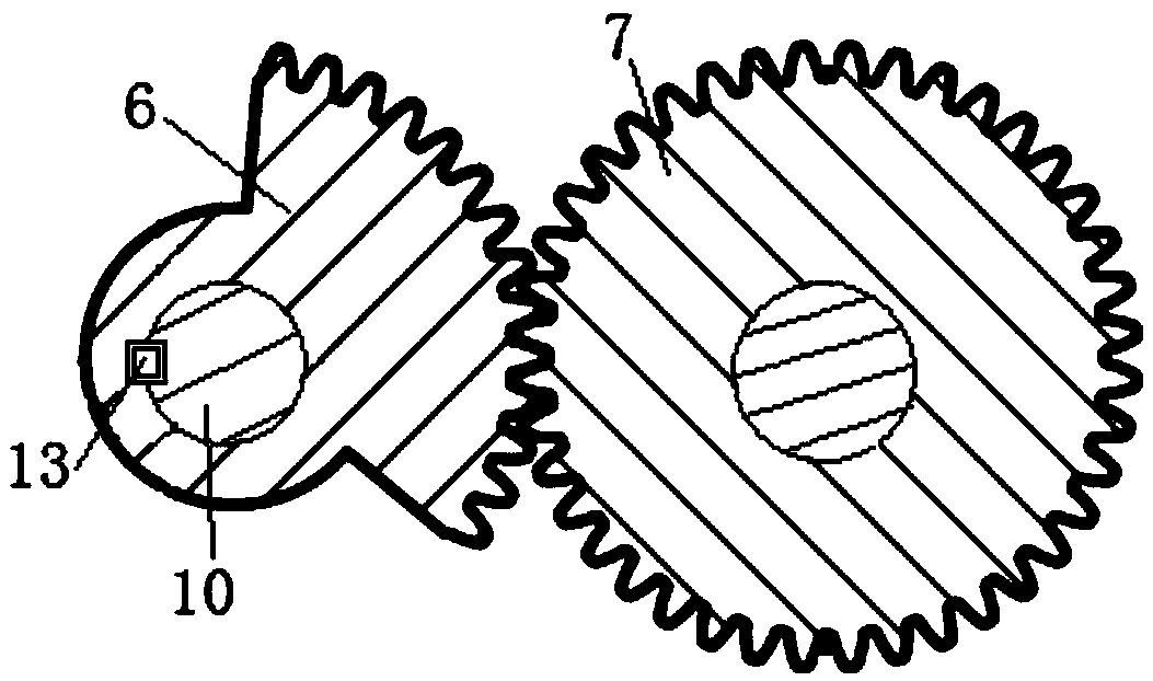
[0021] The seat test bench of the present invention uses a rotating drive structure, such as figure 1 As shown, it includes a sector tooth 6 arranged on the rotating shaft 10, and the sector tooth 6 is meshed with the drive gear 7 for transmission. The rotation driving device also includes a motor 8 arranged on one side of the support 1 , and the output shaft end of the motor 8 is connected with the driving gear 7 . In the process of realizing the rotation, the rotation is started by the motor 8, and the rotation of the drive gear 7 drives the sector teeth 6 engaged with it to rotate, thereby driving the ballast block 5 to rotate within the rotation range of the sector teeth 6.
[0022] In the present invention, if figure 1 As shown, the rotating shaft 10 is provided with a keyway 11, and the...
PUM
 Abstract
Description
Claims
Application Information
 - R&D Engineer
- R&D Manager
- IP Professional
- Industry Leading Data Capabilities
- Powerful AI technology
- Patent DNA Extraction
Browse by: Latest US Patents, China's latest patents, Technical Efficacy Thesaurus, Application Domain, Technology Topic, Popular Technical Reports.
© 2024 PatSnap. All rights reserved.Legal|Privacy policy|Modern Slavery Act Transparency Statement|Sitemap|About US| Contact US: help@patsnap.com