Ceiling machine

A ceiling machine and casing technology, applied in the field of air conditioners, can solve problems such as condensation and ground pollution, and achieve the effects of solving condensation, improving air supply capacity, and reducing barriers.

Pending Publication Date: 2018-11-16
GD MIDEA AIR-CONDITIONING EQUIP CO LTD +1
View PDF0 Cites 1 Cited by
  • Summary
  • Abstract
  • Description
  • Claims
  • Application Information

AI Technical Summary

Problems solved by technology

However, the exposed coaming is prone to condensation and the ...

Method used


Image

  • Ceiling machine
  • Ceiling machine
  • Ceiling machine

Examples


Embodiment Construction

[0046] Embodiments of the present invention are described in detail below, examples of which are shown in the drawings, wherein the same or similar reference numerals designate the same or similar elements or elements having the same or similar functions throughout. The embodiments described below by referring to the figures are exemplary only for explaining the present invention and should not be construed as limiting the present invention.

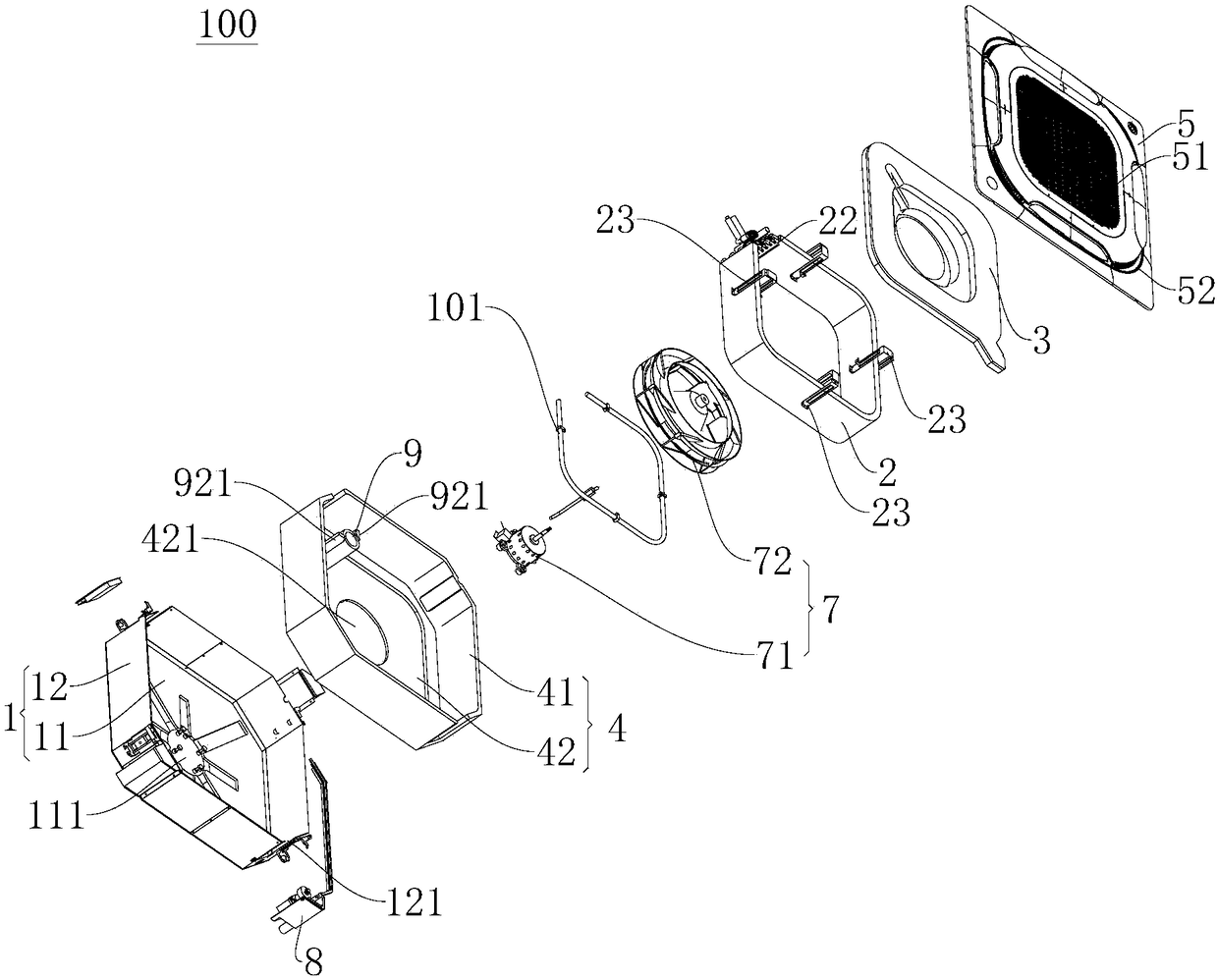
[0047] Refer below Figure 1-Figure 12 The ceiling machine 100 according to the embodiment of the present invention will be described. Wherein, the ceiling machine 100 can be installed on the ceiling or on the wall.

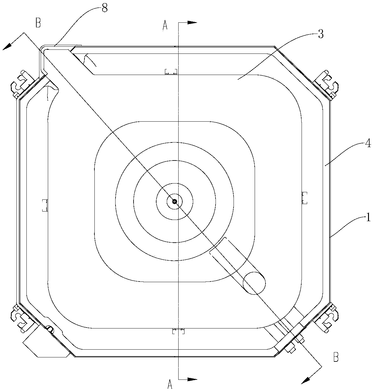
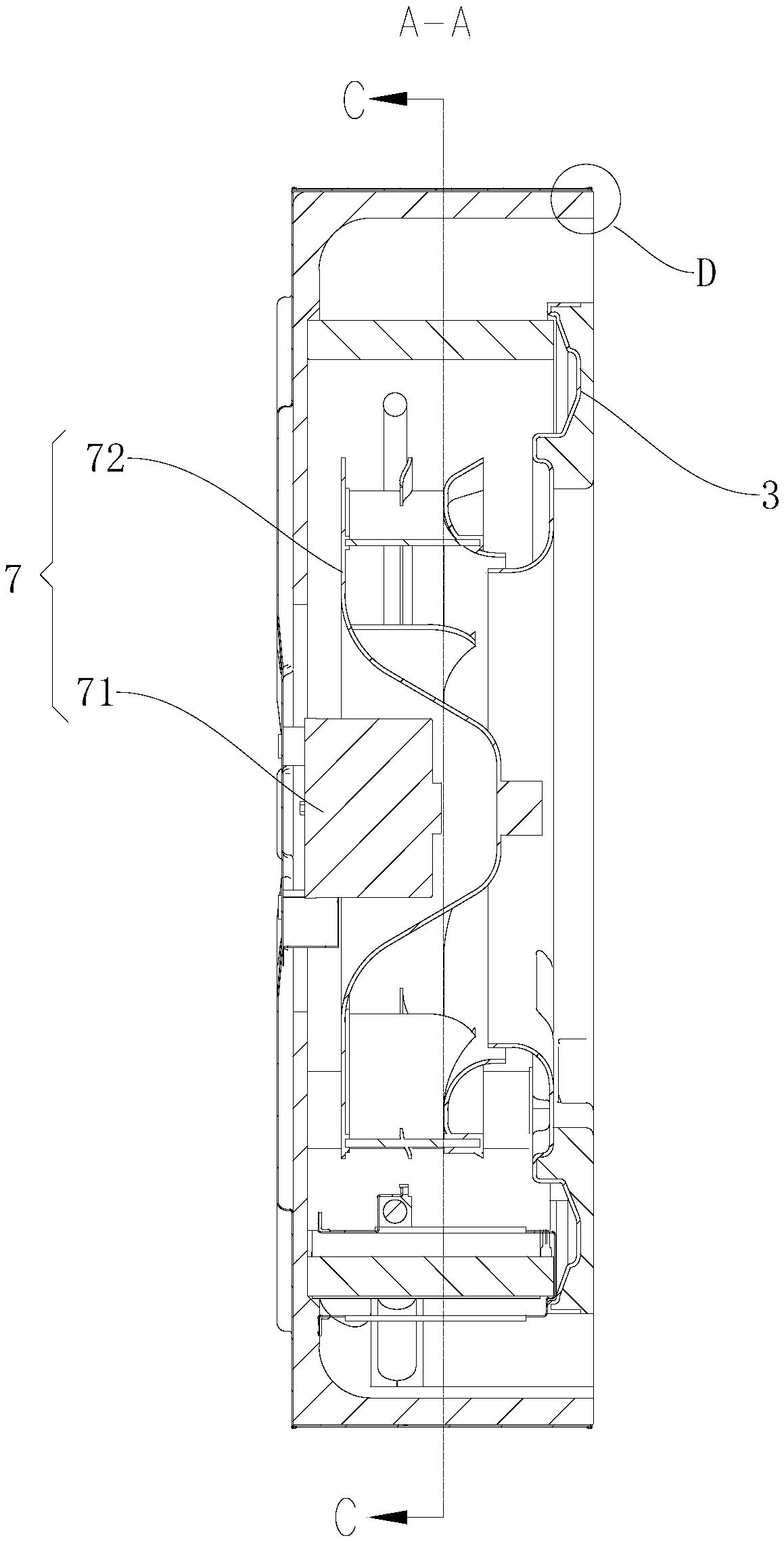
[0048] The ceiling machine 100 according to the embodiment of the present invention includes: a casing 1 , a heat exchanger 2 , a water receiving tray 3 and a thermal insulation member 4 .

[0049] Specifically, refer to figure 1 , the casing 1 includes a top plate 11 and a surrounding plate 12 , the surrounding plate 12...


PUM


Abstract

The invention discloses a ceiling machine. The ceiling machine comprises a machine casing, a heat exchanger, a water receiving tray and a heat insulating member. The machine casing comprises a top plate and a surrounding plate, wherein the surrounding plate is connected with the top plate and surrounds the outer periphery of the top plate. The heat exchanger is arranged in the machine casing and fixed to the top plate by a connecting member, and an annular air outlet duct is formed between the heat exchanger and the surrounding plate in a limited mode. An air inlet duct is formed in the innerside of the heat exchanger in a limited mode. The water receiving tray is disposed on the lower part of the heat exchanger and connected with the connecting member. The heat insulating member comprises a first heat insulating portion, the first heat insulating portion is disposed on the inner wall of the surrounding plate, and the lower end surface of the first heat insulating portion extends downwards to be flush with the lower end surface of the surrounding plate or exceed the lower end surface of the surrounding plate. According to the ceiling machine of the embodiment of the invention, theair supply capacity of the ceiling machine is improved, the air-out noise is reduced, and the air-out of the ceiling machine can be made more uniform; and meanwhile, by extending the lower end surface of the first heat insulating portion downward to be flush with the lower end surface of the surrounding plate or exceed the lower end surface of the surrounding plate, the problem that condensationis prone to being produced on the surrounding plate is effectively solved.

Description

technical field [0001] The invention relates to the technical field of air conditioners, in particular to a ceiling machine. Background technique [0002] In the related art, the water receiving tray of the ceiling machine is usually fixed on the coaming. In order to prevent the thermal insulation from interfering with the assembly of the water receiving tray, there is a gap between the thermal insulation on the inner wall of the coaming and the water receiving tray. However, condensation is likely to be generated on the exposed coaming plate, and the generated condensation will pollute the ground after dripping indoors. Contents of the invention [0003] The present invention aims to solve at least one of the technical problems existing in the prior art. For this reason, an object of the present invention is to provide a ceiling mount, which does not easily generate condensation on the hoarding. [0004] The ceiling machine according to the embodiment of the present inv...

Claims


Application Information

Patent Timeline
IPC IPC(8): F24F1/00F24F13/20F24F13/22F24F13/02F24F13/30
CPCF24F1/0007F24F13/02F24F13/20F24F13/222F24F13/30
Inventor 唐清生
Owner GD MIDEA AIR-CONDITIONING EQUIP CO LTD
Why Eureka
Try Eureka