Bearing needle mounting device and planar thrust bearing needle mounting system

A technology for installing needles and bearings, which is applied in the direction of bearings, bearing components, shafts and bearings, etc. It can solve the problems of low efficiency of needle installation and easy damage to the cage, and achieve the effect of high installation efficiency

Pending Publication Date: 2018-11-16
SUZHOU XINHAO BEARING
View PDF0 Cites 3 Cited by
  • Summary
  • Abstract
  • Description
  • Claims
  • Application Information

AI Technical Summary

Problems solved by technology

[0005] The purpose of the present invention is to provide a bearing needle loading device to solve the technical problems in the prior art that the bearing needle loading efficiency is low and the cage is easily damaged during the needle loading process

Method used


Image

  • Bearing needle mounting device and planar thrust bearing needle mounting system
  • Bearing needle mounting device and planar thrust bearing needle mounting system
  • Bearing needle mounting device and planar thrust bearing needle mounting system

Examples


Embodiment 1

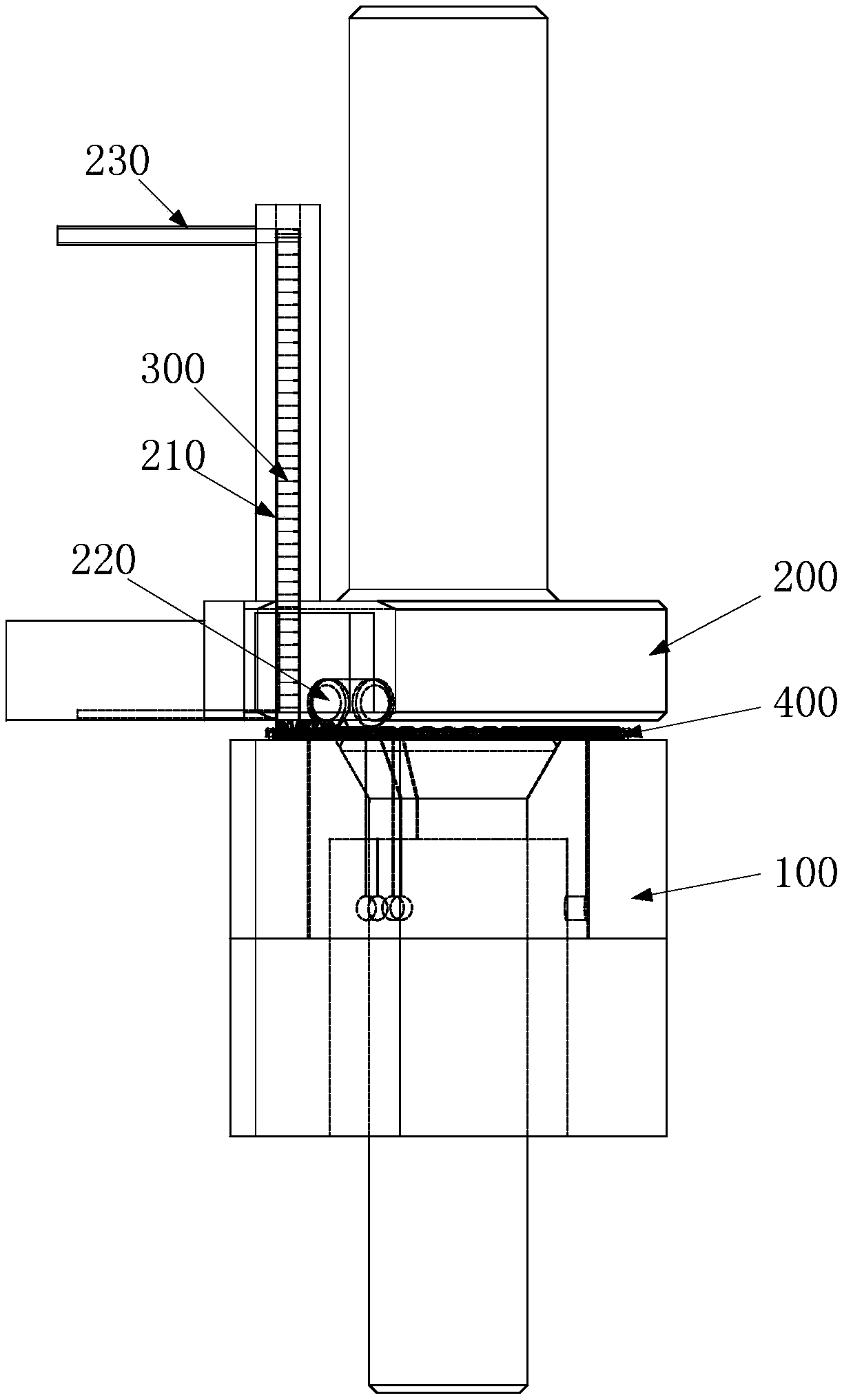
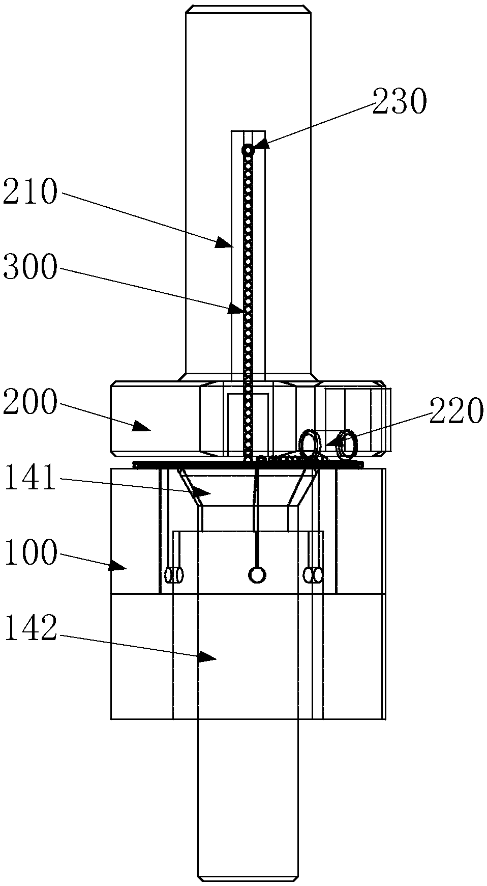
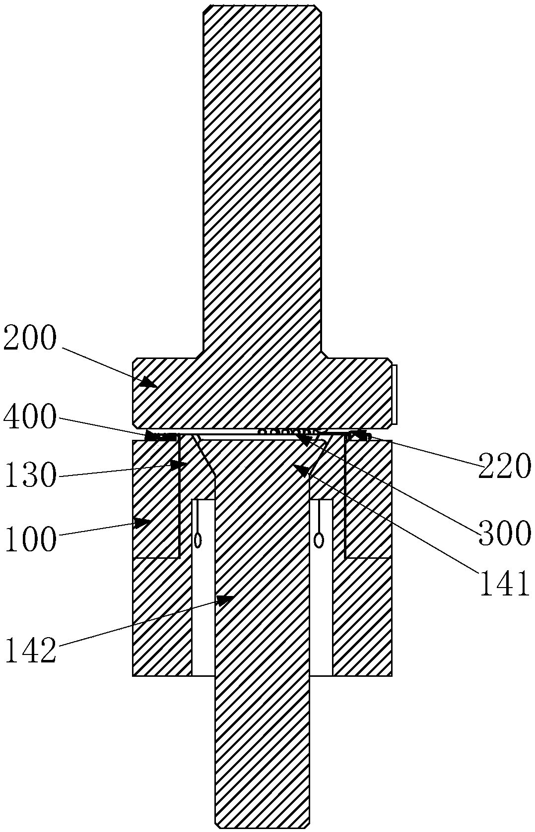
[0038] Such as Figure 1-Figure 7 As shown, the bearing needle loading equipment provided by the embodiment of the present invention includes: a cage positioning device 100, a needle roller positioning device 200 and a driving device, wherein:

[0039] The cage positioning device 100 is used to fix the cage 400 so that the end surface of the cage 400 faces the needle roller positioning device 200 .

[0040] The needle roller positioning device 200 includes at least one needle roller accommodating channel 210 having a feed inlet and a discharge outlet, and at least one pressure roller 220 . The discharge port of the needle roller receiving channel 210 faces the position where the needle roller installation position 410 of the cage 400 fixed on the cage positioning device 100 is located. The pressure roller 220 , the pressure roller 220 is located above the needle roller installation position 410 , and the pressure roller 220 is used to press the needle roller 300 into the need...

Embodiment 2

[0063]Embodiment 2 of the present invention provides a plane thrust bearing needle installation system, including the bearing needle installation device provided in Embodiment 1 above.

[0064] The plane thrust bearing needle loading system has the same advantages as the above-mentioned bearing needle loading equipment over the prior art, and will not be repeated here.

[0065] Further, the plane thrust bearing needle loading system may also include a needle roller feeding device, the needle roller feeding device includes a needle roller chamber, a plurality of needle rollers are placed in the needle roller chamber, a transmission mechanism is arranged in the needle roller chamber, and the needle roller chamber The feeding device sequentially transports the needle rollers in the needle roller chamber to the feed inlet of the needle roller containing channel of the bearing needle loading device through the transmission mechanism, so that the needle rollers enter the needle rolle...


PUM


Abstract

The invention provides a bearing needle mounting device and a planar thrust bearing needle mounting system and relates to the technical field of bearing assembly, and aims to solve the problems that bearing needle mounting efficiency is low and a holder during the mounting process is liable to be damaged. The bearing needle mounting device comprises a holder positioning device, a roller needle positioning device and a driving device, wherein the holder positioning device is used for keep the end surface of the holder face to the roller needle positioning device; the roller needle positioning device includes at least one roller needle accommodating channel, of which the outlet is faced to the position of a roller needle mounting station on the holder fixed on the holder positioning device;at least one press roller is installed rotationally on the roller needle positioning device and is located above the position of the roller needle mounting station; the driving device drives the holder positioning device to rotate axially and move linearly. The bearing needle mounting device is used for mounting a needle onto a bearing and is high in efficiency, and can avoid the risk of damage ofthe holder due to knock.

Description

technical field [0001] The invention relates to the technical field of bearing assembly, in particular to a bearing needle loading device and a planar thrust bearing needle loading system. Background technique [0002] Plane thrust bearings are mainly used to bear axial and radial combined loads mainly under axial loads. This kind of bearings has low friction coefficient, high speed and self-aligning performance. Among them, the needle roller and the cage are the main components of the plane thrust bearing. Generally, there are a large number of needle rollers, which can withstand high thrust loads. [0003] For the needle roller embedding of this type of bearing, manual work is mostly used, and the operator knocks the needle rollers into the cage one by one from the side of the cage. This installation method is labor-intensive and the installation efficiency is low. It is difficult to maintain a balance with the hitting force, so it is easy to cause deformation of the cage...

Claims


Application Information

Patent Timeline
Patent Type & Authority Applications(China)
IPC IPC(8): F16C43/06
CPCF16C43/065F16C2220/48
Inventor 黄伟达张阳平
Owner SUZHOU XINHAO BEARING
Why Eureka
Try Eureka