Method for arc extinguishing by DC load knife switch

A DC load and knife switch technology, which is applied in the direction of electric switches, electrical components, circuits, etc., can solve the problems of short electrical life of DC load knife switches, etc.

Inactive Publication Date: 2018-11-13
柳州螺山科技有限公司
View PDF0 Cites 0 Cited by
  • Summary
  • Abstract
  • Description
  • Claims
  • Application Information

AI Technical Summary

Problems solved by technology

[0004] In order to solve the problem of short service life of the DC load knife switch, the present invention adopts the following technical solutions: see figure 1 , 1 group of mechanical knife switch is connected in parallel with component 6, and then connected in series with 2 groups of mechanical knife switch

Method used


Image

  • Method for arc extinguishing by DC load knife switch
  • Method for arc extinguishing by DC load knife switch
  • Method for arc extinguishing by DC load knife switch

Examples


Embodiment Construction

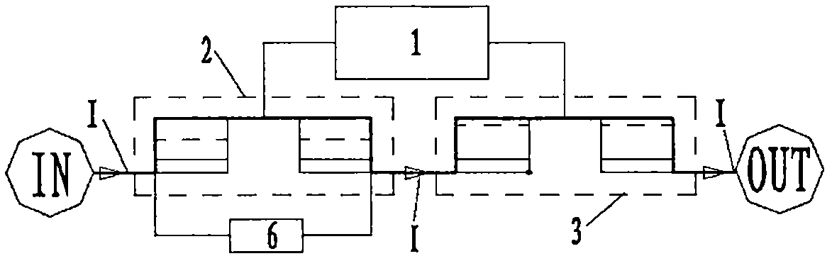
[0011] Such as figure 1 As shown, the load knife switch is connected in series to the DC system through the ports IN and OUT, where the port IN is connected to the positive pole of the DC power supply, and OUT is connected to the load. The first group of mechanical knife switches to be broken is connected in parallel with component 6, and then connected in series with the second group of mechanical knife switches to be broken. The connection of component 6 also has a direction, wherein the + terminal should be connected to the positive pole of the power supply, and the - terminal should be connected to the fixed knives connected to the 1st and 2nd sets.

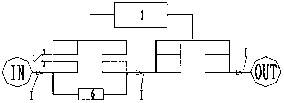
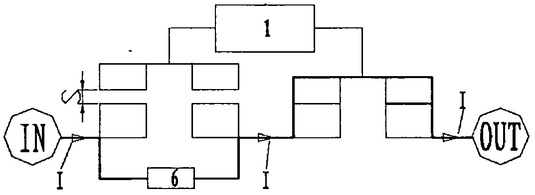
[0012] There is a time difference between group 1 and group 2 of the mechanical knife switch when breaking. This time difference is produced by mechanical design. The two sets of fixed knives of the load knife switch can be designed to have different heights to form a time difference, see figure 2 . It is also possible t...


PUM


Abstract

The invention relates to a load knife switch for a direct current circuit and belongs to the application field of direct current circuits. The load knife switch consists of two sets of knife switchesin series, and the breaking times of the two sets of knife switches are different. A group of knife switches which are first cut off are connected in parallel with a module, which has the functions ofcontrolling the knife switch to cross zero cut off and low-voltage cut off. When the knife switch which is first cut off is cut off, the knife switch which is later cut off has the function of automatic cut-off, so that the knife switch which is later cut off has no arc cut-off. The invention realizes the long service life of the DC load knife switch.

Description

technical field [0001] The invention belongs to the technical field of DC power devices. Especially related to the application of load knife switch in DC circuit. Background technique [0002] The arc generated when breaking the DC circuit is easy to ablate the electrical connection knife edge of the load knife switch. Therefore, the DC circuit with high breaking voltage and the life of the load knife switch are very short, or even unusable. Contents of the invention [0003] The invention provides a method for prolonging the service life of a DC load knife switch with simple principle, scientific and effective, safe and reliable. [0004] In order to solve the problem of short service life of the DC load knife switch, the present invention adopts the following technical solutions: see figure 1 , 1 group of mechanical knife switch is connected in parallel with component 6, and then connected in series with 2 groups of mechanical knife switch. There is a time difference...

Claims


Application Information

Patent Timeline
Patent Type & Authority Applications(China)
IPC IPC(8): H01H9/54
CPCH01H9/547
Inventor 沈红沈治民
Owner 柳州螺山科技有限公司
Why Eureka
Try Eureka