
Combined attitude measurement method in high dynamic environment

A technology of high dynamic environment and measurement method, applied in the direction of measurement device, measurement angle, navigation through velocity/acceleration measurement, etc., which can solve the problem that the measurement device cannot be installed, the space of the rudder blade is small, and the high dynamic rolling requirements of the projectile cannot be met, etc. question

Active Publication Date: 2018-11-13
SHENYANG LIGONG UNIV
View PDF3 Cites 8 Cited by
  • Summary
  • Abstract
  • Description
  • Claims
  • Application Information

AI Technical Summary

Problems solved by technology

On the one hand, conventional gyroscopes cannot meet the high dynamic rolling requirements of the projectile due to the limited range; on the other hand, due to the small internal space of the rudder blade, other measuring devices cannot be installed, and the attitude measurement problem of the rudder blade has always been difficult to solve

Method used


Image

  • Combined attitude measurement method in high dynamic environment
  • Combined attitude measurement method in high dynamic environment
  • Combined attitude measurement method in high dynamic environment

Examples


Embodiment 1

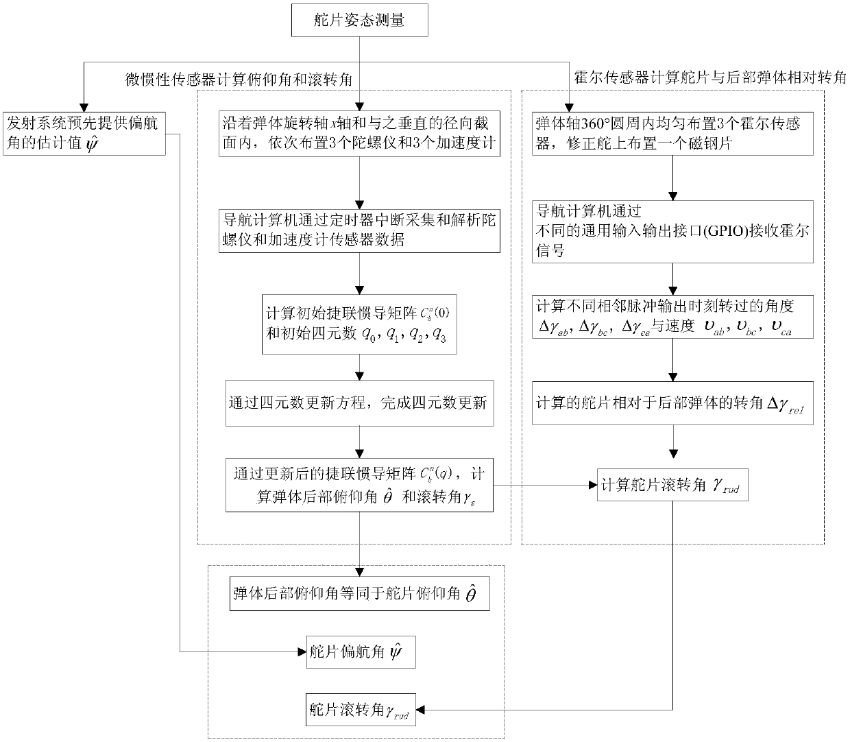
[0120] A combined attitude measurement method in a high-dynamic environment, that is, using a magnetoresistive sensor 1 or a micro-inertial component 3, and at the same time combining a measurement unit for attitude measurement of a measured object to perform basic data collection, and on this basis to calculate the measured The pose of the target object.

[0121] According to the combined attitude measurement method in the high dynamic environment mentioned above, such as figure 1 shown, including the following steps:

[0122]Step 1, in order to measure the attitude of the target measured object, first use the following method to measure the actual measured object to obtain the basic measurement data of the actual measured object; the target measured object is the front of the measured object The actual measured object is the rear part of the measured object; the target measured object is connected to the actual measured object, and there is a relative rotation between the t...

Embodiment 2

[0208] A combined attitude measurement method in a high dynamic environment, that is, using a magnetoresistive sensor 1 or a micro-inertial component 3, and at the same time combining the measurement unit for attitude measurement of the measured object to perform basic data collection, and on this basis to calculate the measured The pose of the target object.

[0209] According to the combined attitude measurement method in the high dynamic environment mentioned above, such as figure 2 shown, including the following steps:

[0210] Step 1, in order to measure the attitude of the target measured object, first use the following method to measure the actual measured object to obtain the basic measurement data of the actual measured object; the target measured object is the front of the measured object The actual measured object is the rear part of the measured object; the target measured object is connected to the actual measured object, and there is a relative rotation between...


PUM


Abstract

The invention belongs to the technical field of attitude measurement application in the navigation technology, and in particular relates to a combined attitude measurement method in a high dynamic environment. In the method, a Hall sensor and a measurement unit for attitude measurement of a measured object are used for basic data acquisition, and the attitude of the measured object is calculated based on basic data.The method disclosed by the invention can be used for overcoming the cost and volume limiting of a spinning projectile correction system in the high dynamic environment to fill up atechnical gap, can replace a conventional attitude measurement method to satisfy the resolving accuracy in practical application, and has the expectable relatively huge economic value and social value.

Description

Technical field [0001] The invention belongs to the technical field of attitude measurement application in navigation technology, and in particular relates to a combined attitude measurement method in a high dynamic environment. technical background [0002] In the prior art, for a rotating projectile in a highly dynamic environment, it has the following attitude characteristics during flight: a slight change in the yaw angle, a low dynamic change in the pitch angle, a high dynamic change in the roll angle, and a roll rate as high as 100r / s or more. The attitude measurement of the corrected rudder in the rotary projectile correction system is the key technology in the process of two-dimensional ballistic correction. On the one hand, conventional gyroscopes cannot meet the high dynamic rolling requirements of the projectile due to the limited range; on the other hand, due to the small internal space of the rudder blade, other measuring devices cannot be installed, and the att...

Claims


Application Information

Patent Timeline
IPC IPC(8): G01C21/00G01C21/16G01C1/00
CPCG01C1/00G01C21/005G01C21/165
Inventor 王磊关英胡学东郝永平
Owner SHENYANG LIGONG UNIV
Learn More