
A drying cabinet for clinical medical equipment

A technology of medical appliances and drying cabinets, which is applied in the direction of drying room/container, drying solid material, drying gas arrangement, etc. It can solve the problems of small support placement gap, left and right shaking and sliding, easy to stack together, etc., to achieve loading and unloading operation process Simplify, enhance structural support strength, and use flexibly and conveniently

Active Publication Date: 2020-05-15
蔡金文
View PDF6 Cites 0 Cited by
  • Summary
  • Abstract
  • Description
  • Claims
  • Application Information

AI Technical Summary

Problems solved by technology

[0007] In order to solve the above-mentioned technical problems, the present invention provides a drying cabinet for clinical medical appliances to solve the problem that the existing medical drying cabinets have too small gaps between the supports and placement of medical appliances and are easy to stack together, and the positioning effect of medical appliances is poor. The process is affected by the blowing of the drying air, which is prone to the problem of shaking from side to side and sliding down

Method used


Image

  • A drying cabinet for clinical medical equipment
  • A drying cabinet for clinical medical equipment
  • A drying cabinet for clinical medical equipment

Examples


Embodiment

[0040] as attached figure 1 to attach Figure 8 Shown:

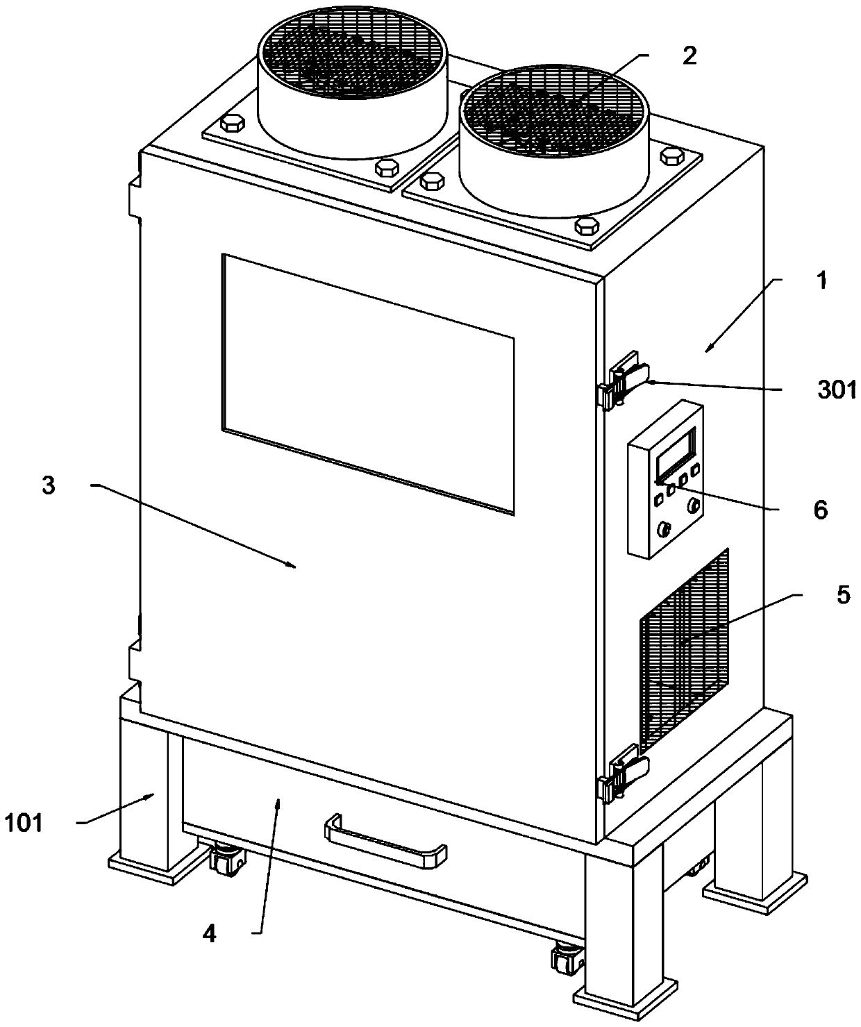
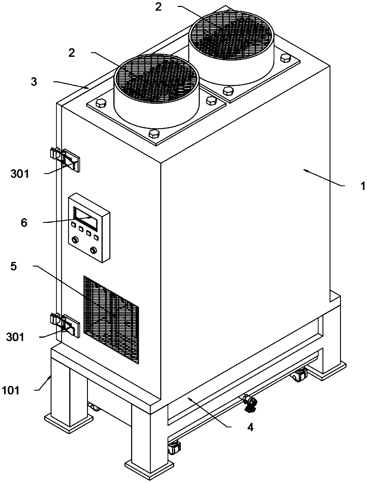
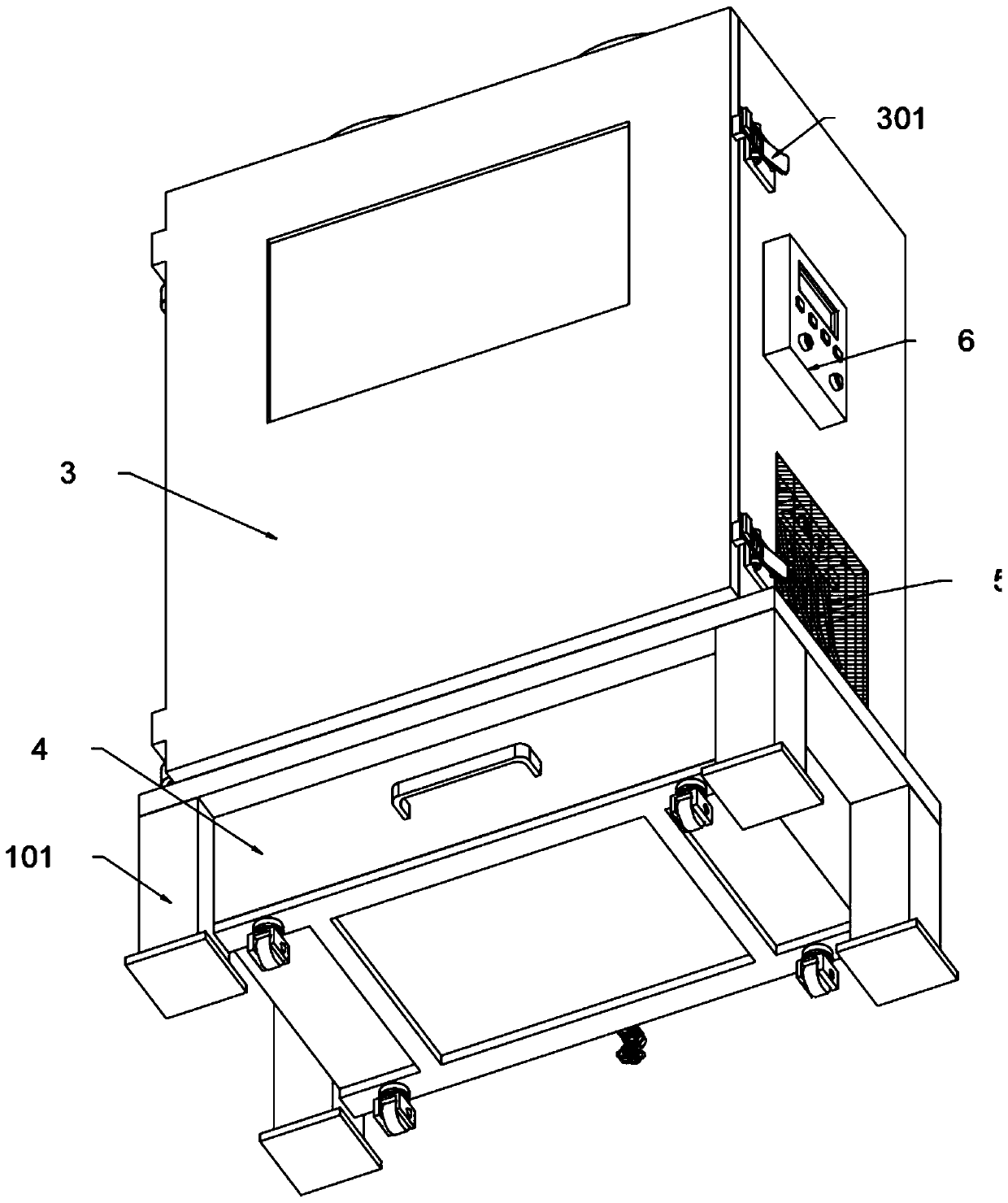
[0041] The present invention provides a drying cabinet for clinical medical appliances, which includes a cabinet body 1, supporting legs 101, an electric heater 2, a cabinet door 3, a push lock 301, a water receiving tank 4, an air outlet tank 5, a control panel 6, surgical scissors 7, Tweezers 8, limit insert frame 9, support plate 10, connecting rod 11, support insert rod 12, limit baffle plate 13, rebound self-locking device 14 and combined support plate 15, and the cabinet body 1 is arranged in a vertical rectangle as a whole There are four supporting legs 101 symmetrically supported at the bottom, and two electric heaters 2 are connected side by side and connected by thread locking at the top; There is a window inlaid in the middle position of the cabinet body 1, and the front edge of the right side wall of the cabinet body 1 is up and down symmetrically welded and provided with two push locks 301, and the cabinet...


PUM


Abstract

The invention provides a clinical medical instrument drying cabinet, comprising limiting baffles, a rebound self-locking device and a combined support plate, wherein a drain pipe communicates with andis supported at the bottom middle position of the rear side wall of a water receiving tank, the water outlet end of the drain pipe is screwed with a copper ball valve, and when the water receiving tank is in a rolling insertion and positioning completed state, the rear side wall of the water receiving tank abuts against a connection abutment plate between two support legs at the rear end; the limiting baffles support, are connected with and are provided with four sets of limiting insertion rings, and sleeve four sets of support insertion rods through the four sets of limiting insertion rings;seven tweezers sliding struts support, are arranged on and are welded on the inner wall of the rear end of the lower half of a cabinet body, and four connecting rods are connected and arranged between each set of tweezers sliding struts. The four sets of support insertion rods are arranged, and the four sets of support insertion rods can support the surgical scissors in the top space of the cabinet body and carry out normal drying operation, so that the four sets of support insertion rods provide convenience for the support placement of the surgical scissors.

Description

technical field [0001] The invention belongs to the technical field of medical drying cabinets, and more specifically relates to a clinical medical appliance drying cabinet. Background technique [0002] After sterilization and disinfection of medical instruments, there is often a lot of disinfectant left on the surface. At this time, it is necessary to use a drying device to dry the medical instruments intensively, which requires the use of a drying cabinet for clinical medical instruments. [0003] After searching, for example, the patent No. CN206959465U discloses a drying device for medical equipment, which includes a box body, a side door is installed on the side wall of the box body, and a fan bracket is installed at the bottom of the inner cavity of the box body. A fan is installed on the fan bracket, and the air supply port of the fan is provided with a heating wire, and the heating wire is connected to an external power supply through a wire. There are no less than...

Claims


Application Information

Patent Timeline
Patent Type & Authority Patents(China)
IPC IPC(8): F26B9/06F26B25/00F26B25/18F26B21/00
CPCF26B9/06F26B21/00F26B25/00F26B25/185
Inventor 蔡金文刘书明
Owner 蔡金文
Learn More