
A detection circuit and a liquid crystal display device

A liquid crystal display device and detection circuit technology, applied in static indicators, instruments, etc., can solve the problems of screen flicker, grayscale screen and solid color screen flicker, inability to accurately detect the quality of the display panel, etc., to suppress flicker and save borders. Effect

Active Publication Date: 2020-11-24
KUSN INFOVISION OPTOELECTRONICS
View PDF15 Cites 0 Cited by
  • Summary
  • Abstract
  • Description
  • Claims
  • Application Information

AI Technical Summary

Problems solved by technology

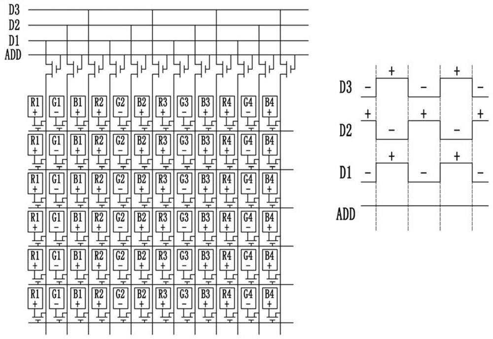
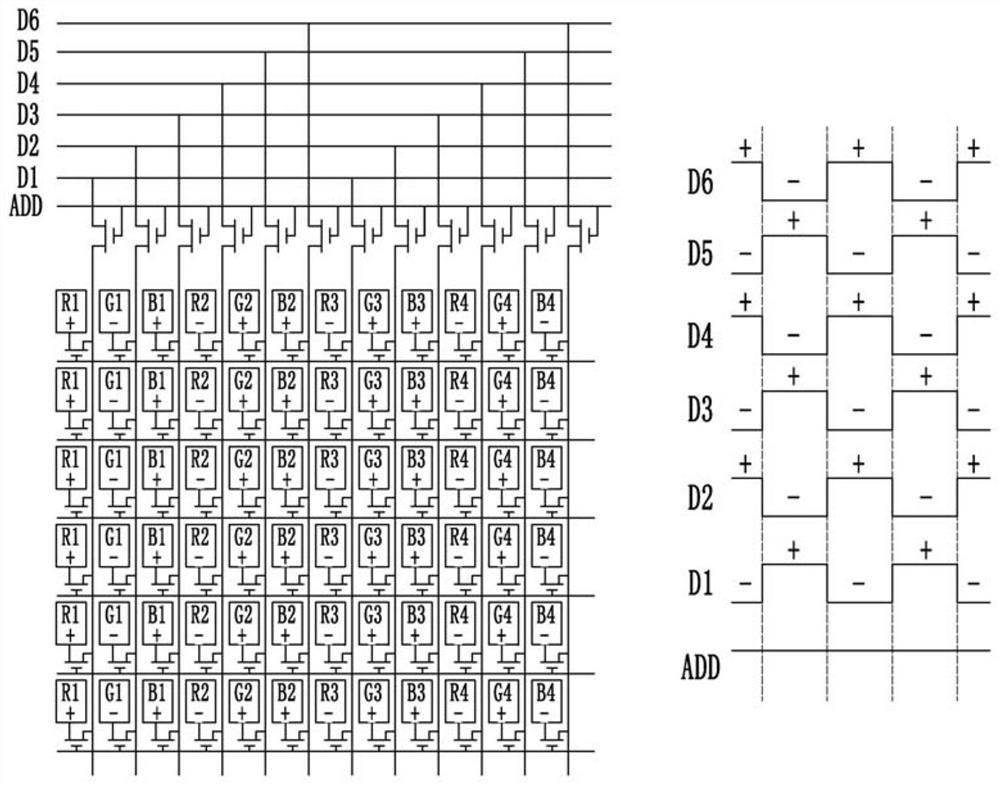
[0003] However, during the detection process of the liquid crystal display device, if the polarities of two adjacent pixels on the display panel are the same, there will be flickering of the grayscale picture and the solid color picture, so that the quality of the display panel cannot be accurately detected.
figure 1 It is the first detection circuit and waveform diagram in the prior art, such as figure 1 As shown, the detection circuit enables the pixels on the display panel to receive corresponding data signals sequentially through a plurality of switching elements, three data signal lines and one control signal line, but in the same frame, two adjacent identical The polarities of the driving voltages of the sub-pixels are basically the same, so the screen will flicker

Method used


Image

  • A detection circuit and a liquid crystal display device
  • A detection circuit and a liquid crystal display device
  • A detection circuit and a liquid crystal display device

Examples


no. 1 example

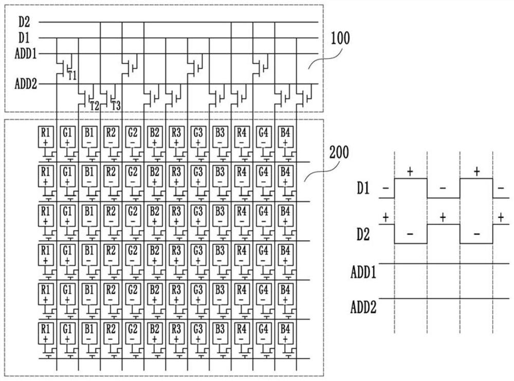
[0025] Please refer to image 3 , image 3 It is a detection circuit and a waveform diagram of an embodiment. R1, R2, R3, etc. in the drawings of this specification represent each first sub-pixel, G1, G2, G3, etc. represent each second sub-pixel, and B1, B2, B3, etc. represent each third sub-pixel.

[0026] Such as image 3 As shown, this embodiment provides a detection circuit 100 for detecting a display panel 200. The display panel 200 includes a plurality of pixel units arranged in an array, and each pixel unit includes three sub-pixels with different colors, respectively the first sub-pixels (R1, R2, R3, etc.), second sub-pixels (G1, G2, G3, etc.) and third sub-pixels (B1, B2, B3, etc.), the detection circuit 100 includes a plurality of first switching elements T1, a plurality a second switching element T2 and a plurality of third switching elements T3. Each first switch element T1 includes a first control terminal, a first channel terminal and a second channel termina...

no. 2 example

[0043] This embodiment also provides a liquid crystal display device, which includes the above-mentioned detection circuit 100 and a display panel 200 .

[0044] In the liquid crystal display device of this embodiment, the detection circuit 100 drives the display panel 200, so that the same sub-pixels on two adjacent pixel units have opposite polarities, so that the flickering of the gray-scale picture and the solid-color picture can be suppressed, so that when the detection The abnormality of pixels on the display panel can be found more accurately, and the frame is saved more.


PUM


Abstract

The present invention provides a detection circuit for detecting a display panel. The detection circuit includes a plurality of first switching elements, a plurality of second switching elements, anda plurality of third switching elements. The polarities of a first data signal and a second data signal are transformed once per frame; two adjacent first sub-pixels or two adjacent second sub-pixelsor two adjacent third sub-pixels respectively receive the first data signal and the second data signal which have opposite polarities respectively through the power-on first switching elements or thepower-on second switching elements or the power-on third switching elements. The present invention also provides a liquid crystal display device. The detecting circuit and the liquid crystal display device of the present invention make the same sub-pixels on two adjacent pixel units have opposite polarities so as to suppress flicker of gray scale and solid color pictures, can accurately find abnormalities of pixels on the display panel during detection, and can save borders.

Description

technical field [0001] The invention relates to the field of liquid crystal display, in particular to a detection circuit and a liquid crystal display device. Background technique [0002] With the development of liquid crystal display technology, people's requirements for display panels are getting higher and higher, and the competition in the LCD panel industry is becoming more and more fierce, which requires panel manufacturers to have superb technology and high yield. [0003] However, during the detection process of the liquid crystal display device, if two adjacent pixels on the display panel have the same polarity, grayscale images and solid color images will flicker, so that the quality of the display panel cannot be accurately detected. figure 1 It is the first detection circuit and waveform diagram in the prior art, such as figure 1 As shown, the detection circuit enables the pixels on the display panel to receive corresponding data signals sequentially through a ...

Claims


Application Information

Patent Timeline
Patent Type & Authority Patents(China)
IPC IPC(8): G09G3/36G09G3/00
CPCG09G3/006G09G3/3614G09G3/3648G09G2320/0247
Inventor 荣誉东
Owner KUSN INFOVISION OPTOELECTRONICS
Learn More