
High-precision engineering-measurement centering rod device

A technology for engineering surveying and centering rods, which is applied in measuring devices, measuring instruments, surveying and mapping, and navigation. It can solve problems such as the decline in surveying and mapping accuracy, poor accuracy of round blisters, and failure to meet the needs of use. It achieves convenient and quick adjustments and reduces adjustments. Time, reduce the effect of equipment maintenance costs

Pending Publication Date: 2018-11-06
刘谦
View PDF0 Cites 2 Cited by
  • Summary
  • Abstract
  • Description
  • Claims
  • Application Information

AI Technical Summary

Problems solved by technology

In order to ensure the measurement accuracy, the center of the prism group is required to be plumb to the ground point. However, due to various factors in the actual use process, the center of the prism group and the ground point are not plumb, so it is necessary to correct the round blister, but the normal accuracy of the round blister Poor, resulting in a decline in surveying and mapping accuracy, unable to meet the needs of use

Method used


Image

  • High-precision engineering-measurement centering rod device
  • High-precision engineering-measurement centering rod device
  • High-precision engineering-measurement centering rod device

Examples


Embodiment Construction

[0027] Below in conjunction with accompanying drawing and embodiment, further elaborate the present invention. In the following detailed description, certain exemplary embodiments of the invention are described by way of illustration only. Needless to say, those skilled in the art would realize that the described embodiments can be modified in various different ways, all without departing from the spirit and scope of the present invention. Accordingly, the drawings and description are illustrative in nature and not intended to limit the scope of the claims.

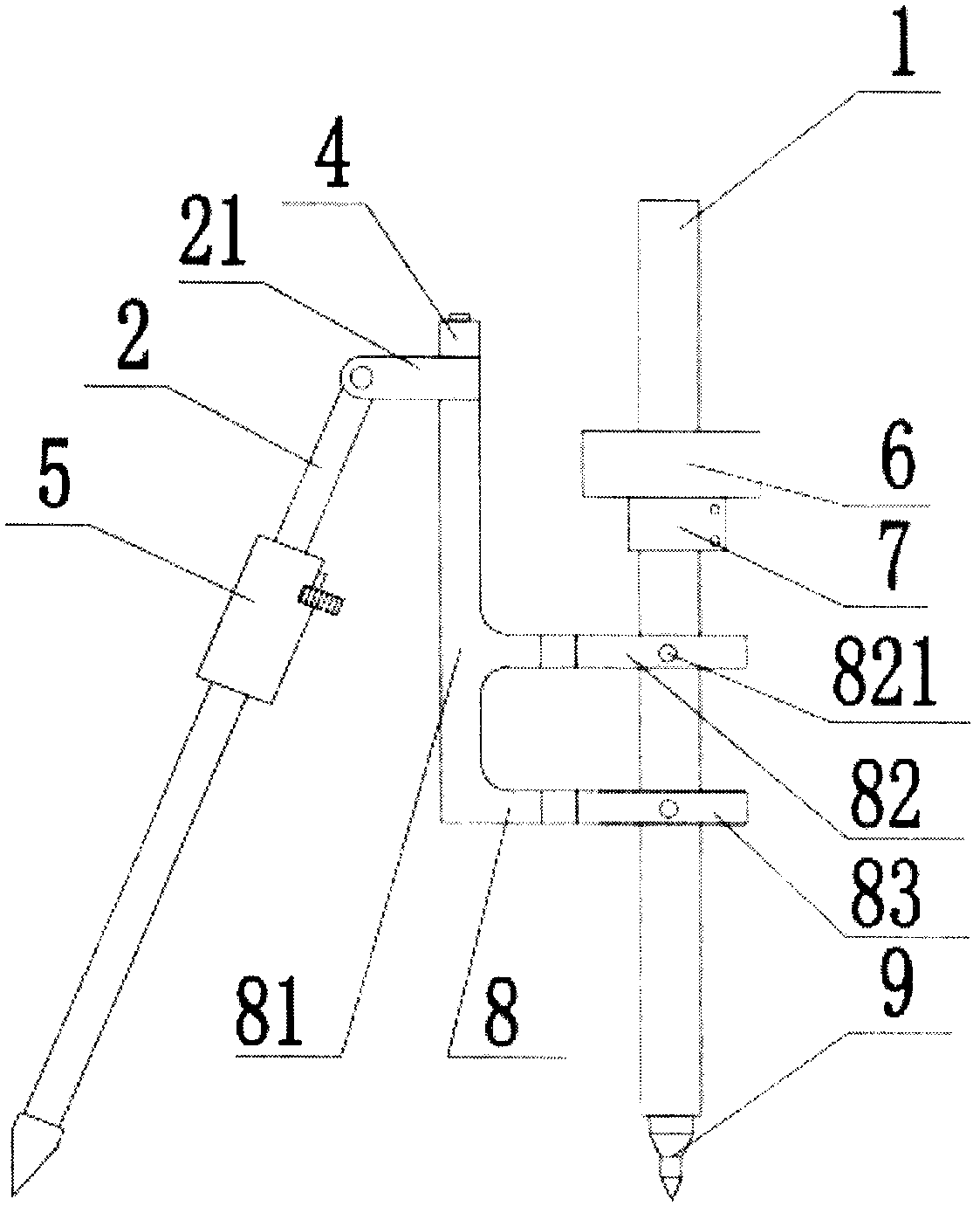
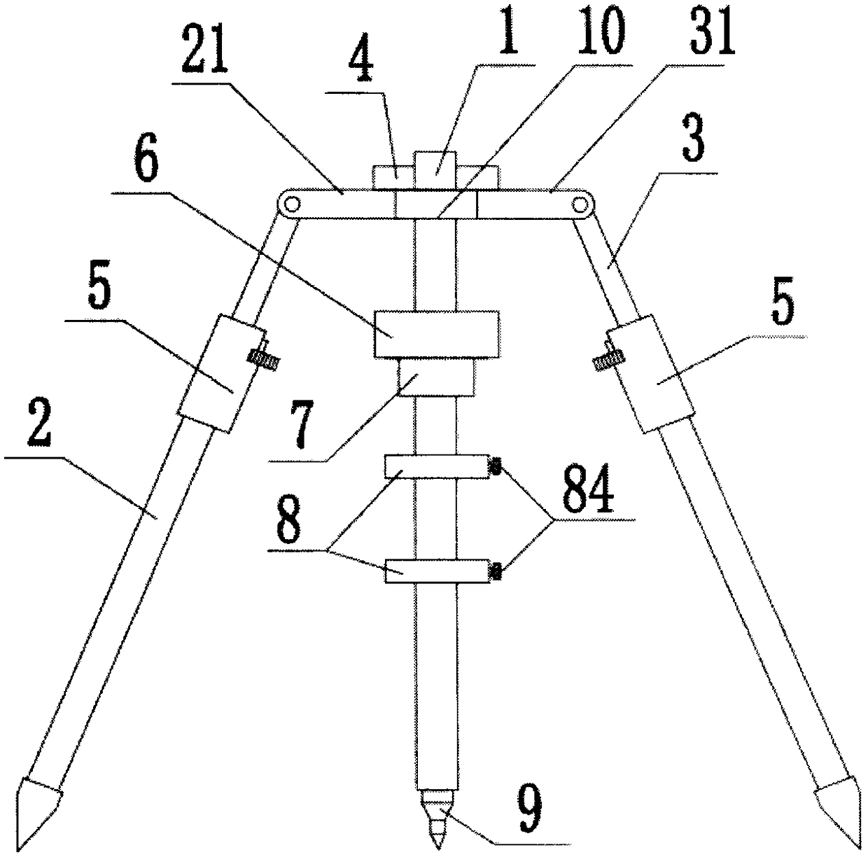
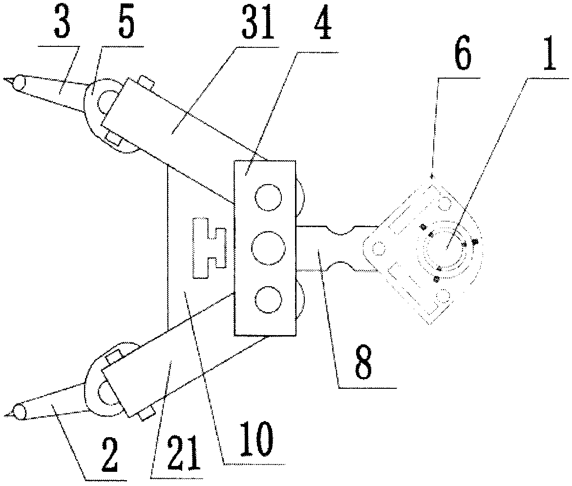
[0028] Such as Figure 1 to Figure 6 As shown, the centering rod device for high-precision engineering survey according to Embodiment 1 of the present invention includes a centering rod 1, a stopper 10, a detachable conical head 9 arranged at the bottom end of the centering rod 1, The leveler assembly 6, the F-shaped bracket 8, the left support assembly 2 and the right support assembly 3 which are symmetrically arranged...


PUM

PropertyMeasurementUnit
Lengthaaaaaaaaaa

Abstract

The invention discloses a high-precision engineering-measurement centering rod device. The high-precision engineering-measurement centering rod device comprises a centering rod, a limiting device, a detachable conical head arranged at the bottom end of the centering rod, a water level assembly fixedly connected on the centering rod, a left supporting assembly and a right supporting assembly, wherein the left supporting assembly and the right supporting assembly are symmetrically arranged on the two sides of the centering rod; a left connecting rod and a right connecting rod are fixedly connected with the top end of an F-shaped support separately, and the F-shaped support is fixedly connected with the centering rod; a fine adjustment assembly and a fast adjustment assembly which are capableof adjusting the length of the left supporting assembly and the length of the right supporting assembly are also arranged on the left supporting assembly and the right supporting assembly respectively; the water level assembly comprises a right pipe water level and a left pipe water level which are perpendicular to each other, and the two side edges of the limiting device are in contact cooperation with the left connecting rod and the right connecting rod respectively so that the left connecting rod and the right connecting rod can be parallel to the right pipe water level and the left pipe water level respectively. By means of the high-precision engineering-measurement centering rod device, the measurement precision of the centering rod can be effectively increased, adjustment of the water levels can be achieved through the fine adjustment assembly and the fast adjustment assembly, and different using requirements are met.

Description

technical field [0001] The invention relates to the technical field of surveying and mapping equipment, in particular to a centering rod device for high-precision engineering survey. Background technique [0002] As an indispensable centering device in surveying and mapping, the surveying and mapping centering rod has a wide range of uses in surveying and mapping. At present, when the existing centering rod is working, the lower end of the centering rod is used to align the tip of the centering rod with the target point to be measured, and the two support rods are adjusted to center the round blister. The prism group is plumb with the underground target point. In order to ensure the measurement accuracy, the center of the prism group is required to be plumb to the ground point. However, due to various factors in the actual use process, the center of the prism group and the ground point are not plumb, so it is necessary to correct the round blister, but the normal accuracy o...

Claims


Application Information

Patent Timeline
IPC IPC(8): G01C15/08
CPCG01C15/08
Inventor 刘谦谢振波刘玉伟申雄权张磊孙伟亮潘强英姜源张鑫刘云张良韩云鹏郝佩王培育薛彪
Owner 刘谦
Learn More