DC transmission and distribution power flow control device and its control strategy and application method

A power flow and control device technology, applied in power transmission AC networks, AC networks with the same frequency from different sources, etc., can solve the problems of complex control, high cost, high power consumption, etc., and achieve high economic effects.

Active Publication Date: 2022-04-12
YANGZHOU UNIV
View PDF1 Cites 0 Cited by
  • Summary
  • Abstract
  • Description
  • Claims
  • Application Information

AI Technical Summary

Problems solved by technology

[0004] The purpose of the present invention is to provide a DC transmission and distribution power flow control device to solve the problems of high cost, complicated control and large power consumption in the existing DC power distribution scheme

Method used


Image

  • DC transmission and distribution power flow control device and its control strategy and application method
  • DC transmission and distribution power flow control device and its control strategy and application method
  • DC transmission and distribution power flow control device and its control strategy and application method

Examples


Embodiment 1

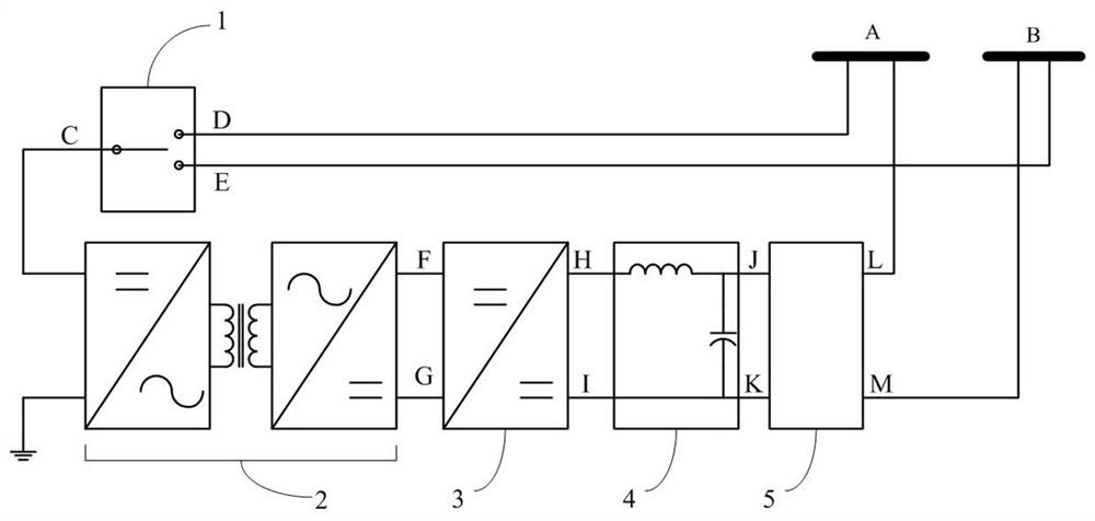
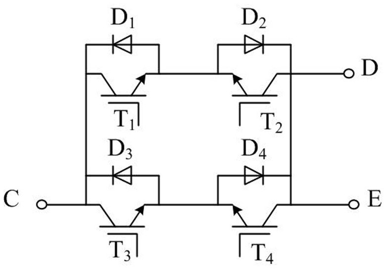
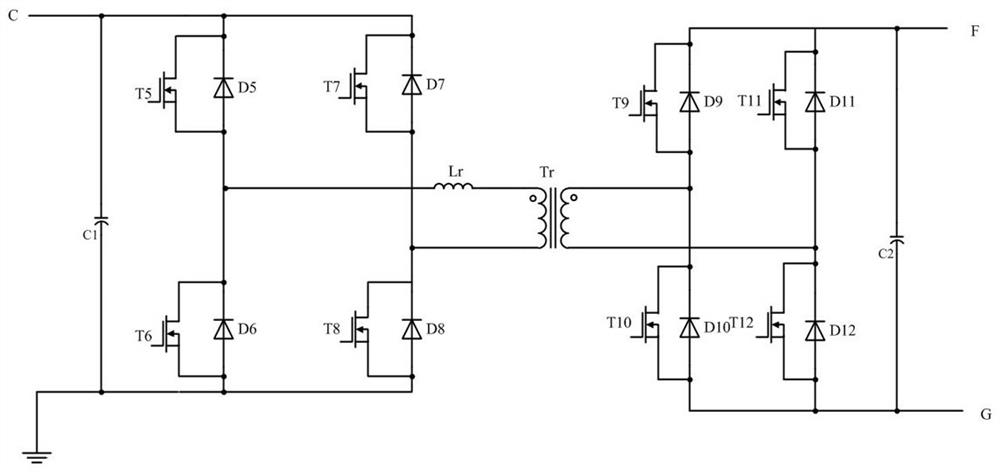
[0034] Such as Figure 1-5 A power flow control device for DC transmission and distribution shown includes a bus switch 1 , an isolated DC-DC converter 2 with reversible power flow, a four-quadrant DC-DC converter 3 , a filter circuit 4 , and a port protection circuit 5 .

[0035] One end of the bus switch is connected to the input end of the isolated DC-DC converter 2; the output end of the isolated DC-DC converter 2 is connected to the input end of the four-quadrant DC-DC converter 3, and the four-quadrant DC-DC converter 3 The output terminal of the filter circuit 4 is connected to the filter circuit 4, and the two output ports of the filter circuit 4 are connected between the two DC buses A and B; the port protection circuit 5 is respectively connected between the two output ports of the filter circuit 4 and the ground; the power flow adjustment The low-level control algorithm controls the magnitude and direction of the current between the two DC buses A and B, and at the ...

Embodiment 2

[0049] Such as Figure 8 As shown, an application method of a DC transmission and distribution power flow control device, when there are three DC buses in the power supply system, three DC transmission and distribution power flow control devices 6, 7, and 8 are correspondingly configured, and each DC transmission and distribution power flow control device The power flow control devices 6, 7, and 8 are connected between every two adjacent DC buses to adjust the power flow between the DC buses.

Embodiment 3

[0051] Such as Figure 9 As shown, an application method of a DC transmission and distribution power flow control device, when there are three DC buses in the power supply system, correspondingly equipped with three DC transmission and distribution power flow control devices 9, 10, 11, and the three DC transmission and distribution power flow control devices The control devices 9, 10, 11 are connected in series to form an annular multi-port structure, and each port is connected to a DC bus to regulate the power flow between the DC buses.


PUM


Abstract

The invention discloses a DC power flow control device and its control strategy in the field of power transmission and distribution, including a bus switch, an isolated DC-DC converter, a four-quadrant DC-DC converter, a filter circuit and port protection. circuit, the output end of the busbar transfer switch is connected to the input end of the isolated DC-DC converter, the input end of the busbar transfer switch is connected to the two DC buses A and B, and the output end of the isolated DC-DC converter is connected to the four-quadrant DC- The input end of the DC converter and the output end of the four-quadrant DC-DC converter are connected to the filter circuit. The two output ports of the filter circuit are connected to the two DC buses A and B through the port protection circuit to solve the existing DC power distribution solution. It can be used in DC power transmission and distribution due to the problems of high cost, complex control and large power consumption.

Description

technical field [0001] The invention relates to a power transmission and distribution control circuit, in particular to a direct current power transmission and distribution device. Background technique [0002] DC power transmission technology is one of the main means of high-power electric energy transmission at present. Its advantage is that its transmitted electric power is not affected by the inductance of the transmission line, and avoids the situation that the reactive current in the AC transmission system affects the transmission efficiency. So far, the radial mode of DC transmission and distribution has mostly been adopted, that is, one power generation node has multiple locations; no multi-DC transmission network has yet been formed. In the field of power distribution, DC power distribution is currently mainly used in centralized power consumption environments, such as aircraft power systems and high-power communication power systems. [0003] At present, the power...

Claims


Application Information

Patent Timeline
Patent Type & Authority Patents(China)
IPC IPC(8): H02J3/36H02J3/06
CPCH02J3/06H02J3/36Y02E60/60
Inventor 蒋伟吕思龙黄明
Owner YANGZHOU UNIV
Why Eureka
Try Eureka