
Rotary heating type curing furnace for composite propeller

A technology of rotating heating and composite materials, applied in applications, household appliances, household components, etc., can solve problems such as temperature difference, large temperature difference, and affecting the quality of composite material propellers

Active Publication Date: 2018-11-02
安徽劲旋风航空科技有限公司
View PDF1 Cites 2 Cited by
  • Summary
  • Abstract
  • Description
  • Claims
  • Application Information

AI Technical Summary

Problems solved by technology

There is a large temperature difference inside the existing composite material propeller curing furnace, and the temperature difference between the upper, lower, left and right sides of the furnace is relatively large, especially after being placed in the propeller mold, there is a large temperature difference between the upper and lower molds of the mold, which seriously affects the composite material. Material propeller quality

Method used


Image

  • Rotary heating type curing furnace for composite propeller
  • Rotary heating type curing furnace for composite propeller
  • Rotary heating type curing furnace for composite propeller

Examples


Embodiment Construction

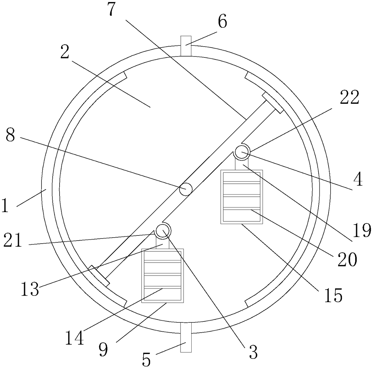
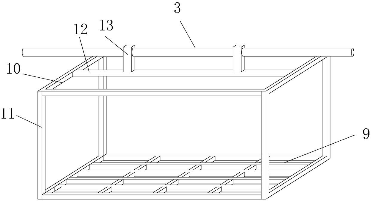
[0016] Such as Figure 1-Figure 5 as shown, figure 1 It is a structural schematic diagram of a rotary heating type curing furnace for a composite material propeller proposed by the present invention; figure 2 It is a structural schematic diagram of the first mold frame in a rotary heating type curing furnace for a composite material propeller proposed by the present invention; image 3 It is a structural schematic diagram of the second grid plate in a rotary heating type curing furnace for a composite material propeller proposed by the present invention; Figure 4 It is a structural schematic diagram of the second mold frame in a rotary heating type curing furnace for a composite material propeller proposed by the present invention; Figure 5 It is a structural schematic diagram of the fourth grid plate in a rotary heating type curing furnace for a composite material propeller proposed by the present invention.

[0017] refer to Figure 1-Figure 5 , a rotary heating type ...


PUM


Abstract

The invention discloses a rotary heating type curing furnace for a composite propeller. A barrel-shaped curing chamber is formed in a furnace body. A plurality of rotating shafts are arranged in the curing chamber at interval along the axial direction of the furnace body, and the two ends of each rotating shaft are connected with the inner wall of the furnace body in a sliding mode. A center shaftis arranged at the center of the curing chamber along the axial direction of the furnace body, and the center shaft passes through the centers of the rotating shafts in order and is fixedly connectedwith the rotating shafts. A first support shaft and a second support shaft are positioned on the two sides of the center shaft and are connected with the rotating shafts, and a first mould rack and asecond mould rack are respectively hinged with the first support shaft and the second support shaft. According to the rotary heating type curing furnace, the rotating shafts are driven by the centershaft to rotate, and the first mould rack and the second mould rack are driven by the rotating shafts to move up and down, so that hot air in the curing chamber can be guided to flow, and the upper and lower temperatures of the curing chamber are uniform. Therefore, the difference of the upper and lower mould temperatures of a mould is within + / -1 or so, the temperature requirement of the composite propeller in the forming process can be met, and the quality of the propeller is ensured.

Description

technical field [0001] The invention relates to the technical field of propeller curing, in particular to a rotary heating type curing furnace for composite material propellers. Background technique [0002] The propeller is a key part of the power machinery in a helicopter or other small aircraft. Compared with traditional metal propellers, composite propellers have many advantages such as light weight, high rigidity, low vibration, strong weather resistance and flexible design. There is a large temperature difference inside the existing composite material propeller curing furnace, and the temperature difference between the upper, lower, left and right sides of the furnace is relatively large, especially after being placed in the propeller mold, there is a large temperature difference between the upper and lower molds of the mold, which seriously affects the composite material. The quality of the material propeller. Contents of the invention [0003] In order to solve t...

Claims


Application Information

Patent Timeline
IPC IPC(8): B29C35/04B29L31/08
CPCB29C35/002B29C35/045B29C2035/046B29L2031/087
Inventor 南雍
Owner 安徽劲旋风航空科技有限公司
Learn More