Gear processing device

A processing device and gear technology, which is applied in gear tooth manufacturing devices, metal processing equipment, belts/chains/gears, etc., can solve the problems of reduced processing efficiency, high labor intensity, and low efficiency, so as to ensure grinding efficiency and improve The effect of grinding efficiency

Active Publication Date: 2019-05-24
SUZHOU HAOLI CULTURE MEDIA TECH CO LTD +1
View PDF8 Cites 0 Cited by
  • Summary
  • Abstract
  • Description
  • Claims
  • Application Information

AI Technical Summary

Problems solved by technology

Although it is a mechanized operation, only one burr in the tooth groove can be polished at a time, and the efficiency is relatively low; after the grinding is completed, the gear needs to be removed manually, which is labor-intensive and reduces the processing efficiency

Method used


Image

  • Gear processing device
  • Gear processing device
  • Gear processing device

Examples


specific Embodiment approach

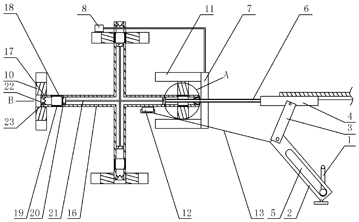
[0030] When the stepper motor rotates counterclockwise, it drives the toggle lever 1 to rotate to figure 1 When the position is shown, the toggle rod 1 drives the swing block 2 to swing to the leftmost, and now the swing block 2 pulls the slider 4 through the connecting block 3 to move to the leftmost, and the resisting plate 12 supports the rotating tube 16 at this time. In the process of slider 4 sliding to the left, it drives the unloading pipe 6 and the grinding disc 7 to move to the left. The burrs are polished.

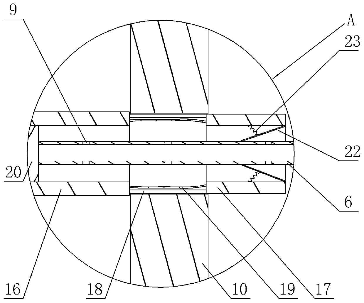
[0031] Such as figure 2 As shown, in the process that the discharge pipe 6 continues to move to the left, the discharge pipe 6 is in contact with the fan-shaped plate 22 at the right end of the support pipe 17, and the fan-shaped plate 22 is separated under the thrust of the discharge pipe 6, and the discharge pipe 6 enters In the support tube 17, the gas in the support tube 17 and the rotating tube 16 overflows from the discharge tube 6 through the pores 9, ...


PUM


Abstract

The invention relates to the field of gear machining, in particular to a gear machining device. The gear machining device comprises a polishing and discharging mechanism, a resisting mechanism and a rotating mechanism, wherein the polishing and discharging mechanism comprises a polishing and discharging unit and a transfer unit for driving the polishing and discharging unit to reciprocate; the polishing and discharging unit comprises a discharging pipe and a polishing disc; holes are formed in the wall of the discharging pipe; polishing teeth matched with tooth grooves are arranged on the polishing disc; the rotating mechanism comprises a plurality of rotating units; each rotating unit comprises a rotating pipe, a plurality of supporting rods and a supporting pipe; the middle part of the rotating pipe is rotatably arranged on a rack; the plurality of supporting rods are fixed at the two ends of the rotating pipe; the supporting pipe is fixedly connected to the rotating pipe through thesupporting rods; air bags with openings at two ends are connected between the rotating pipe and the supporting pipe; the supporting rods are distributed on the peripheries of the air bags; two pistons are arranged in the rotating pipe in a sliding manner and are connected through a connecting pipe; and an air leaking mechanism which is matched with the discharging pipe and leaks air in the air bags is arranged at the free end of the supporting pipe. The gear machining device adopting the technical scheme can improve the polishing efficiency of gears.

Description

technical field [0001] The invention relates to the field of gear processing, in particular to a gear processing device. Background technique [0002] A gear is a mechanical element that transmits motion and power through continuous meshing of gear teeth. Due to the smooth transmission of gears, it is widely used in mechanical transmission and the entire mechanical field. Gears can be divided into four categories, including spur gears, bevel gears, ring gears, and special purpose gears. [0003] During the processing of gears, the burrs in the tooth grooves need to be polished. The existing gear grinding is mainly to drive the gear to rotate intermittently through the motor, and then control the cutting knife to move to the same position regularly through the mechanical arm to cut the burrs in the tooth groove. Although it is a mechanized operation, it can only grind the burrs in one tooth groove at a time, and the efficiency is relatively low; and after the grinding is co...

Claims


Application Information

Patent Timeline
Patent Type & Authority Patents(China)
IPC IPC(8): B23F19/00B23F23/06B23F23/12
CPCB23F19/00B23F23/06B23F23/12
Inventor 陈世刚
Owner SUZHOU HAOLI CULTURE MEDIA TECH CO LTD
Why Eureka
Try Eureka