Pressure regulating valve

A technology of pressure regulation and regulator, applied in the field of pressure regulating valves, which can solve the problems of high cost and achieve the effect of low wear and compact size

Active Publication Date: 2018-10-23
FESTO AG & CO KG
View PDF6 Cites 0 Cited by
  • Summary
  • Abstract
  • Description
  • Claims
  • Application Information

AI Technical Summary

Problems solved by technology

The production of pressure control valves is associated with relatively high costs, since a relatively...

Method used


Image

  • Pressure regulating valve
  • Pressure regulating valve
  • Pressure regulating valve

Examples


Embodiment Construction

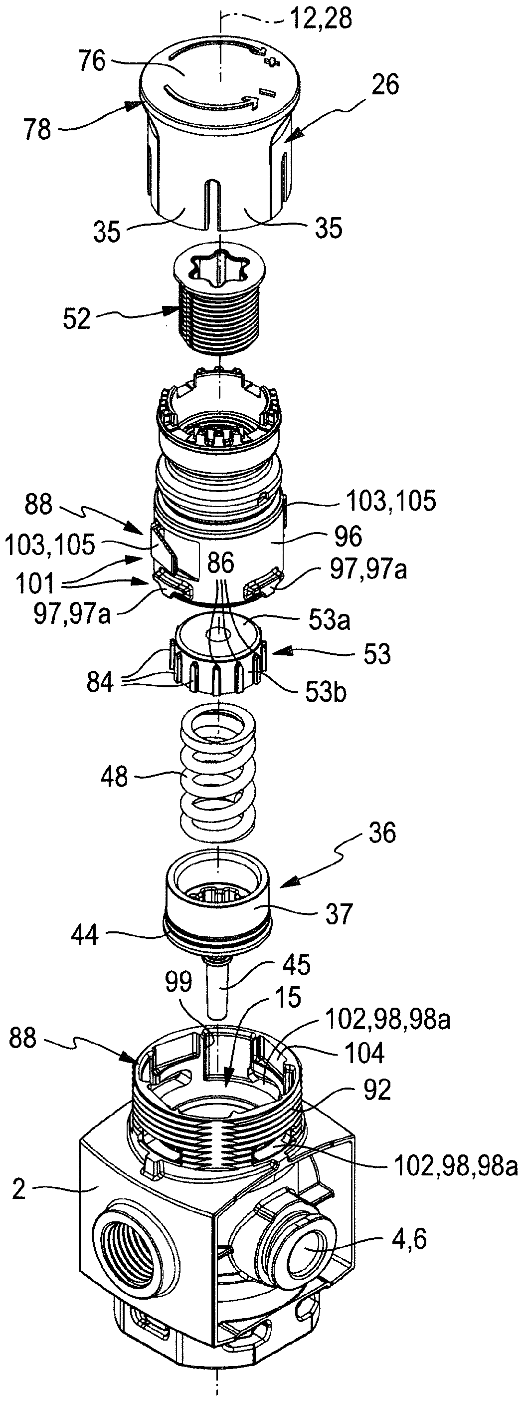
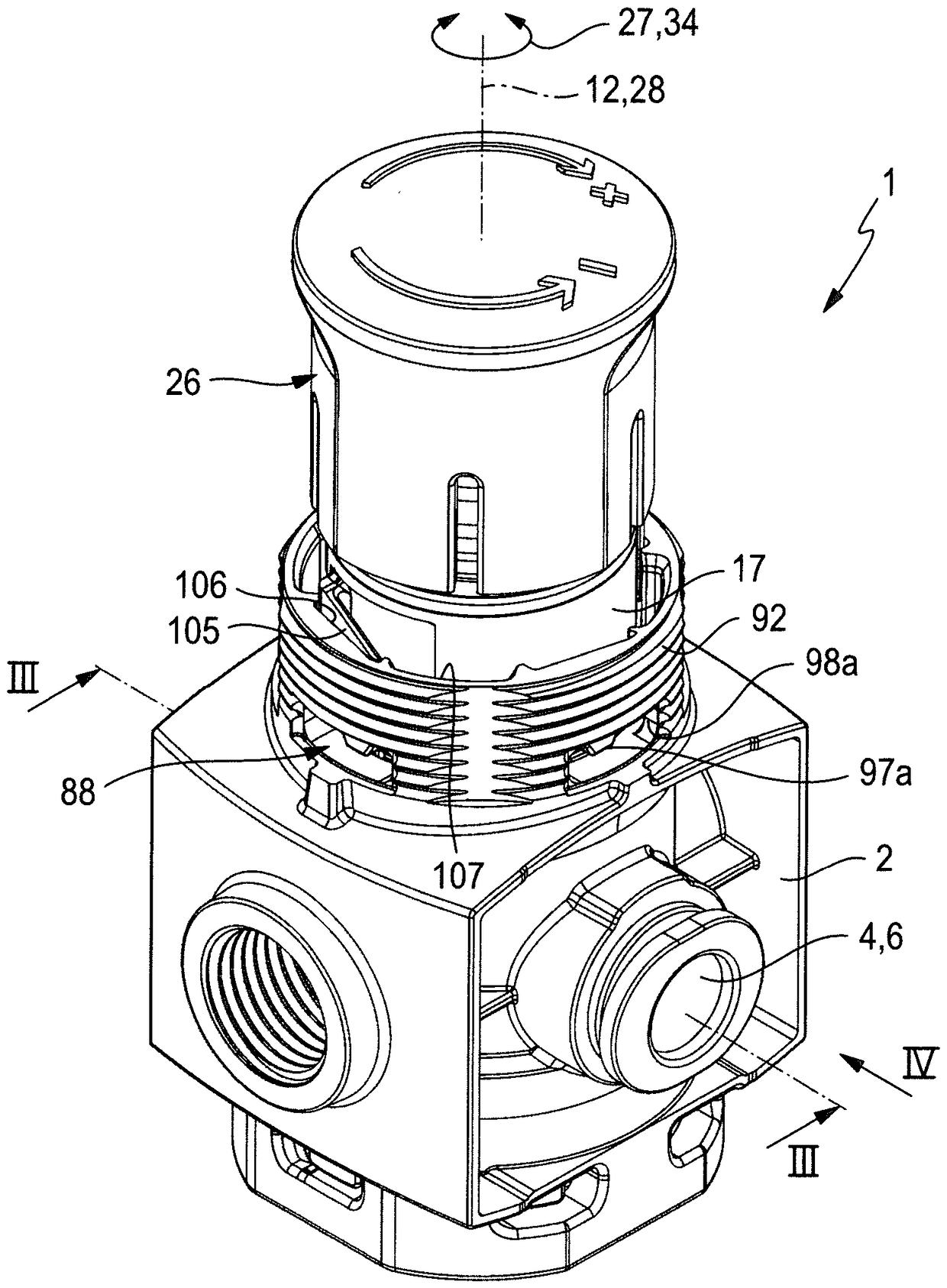
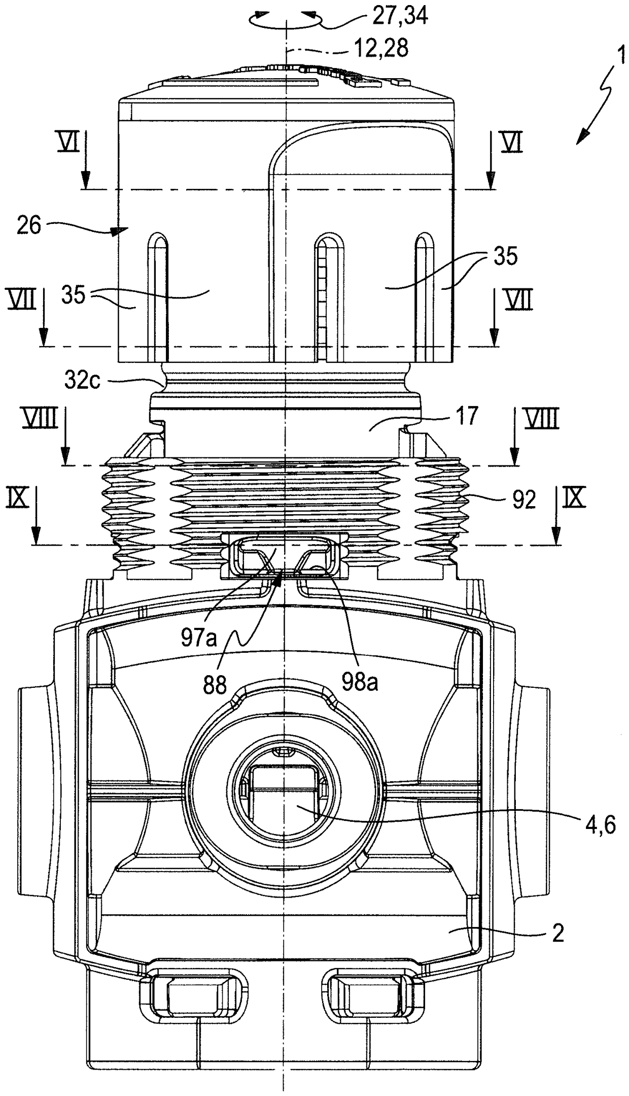
[0036] The pressure regulating valve 1 illustrated in the drawing has a regulator housing 2 in which flow channels run, referred to as primary channel 3 and secondary channel 4 , which At different (in particular opposite) housing outer surfaces of the regulator housing 2 , there is an opening via a primary connection 5 and a secondary connection 6 .

[0037] During operation of the pressure regulating valve 1 , compressed air is supplied via the primary connection 5 at the primary pressure, which is regulated to the secondary pressure while flowing through the regulator housing 2 and is at this The ground under the secondary pressure can be tapped off at the secondary connection 6 . In general, the secondary pressure is lower than the primary pressure and its height can be predetermined as required by a corresponding adjustment of the pressure regulating valve 1 .

[0038] The primary channel 3 and the secondary channel 4 are connected to one another through an overflow open...


PUM


Abstract

The invention provides a pressure regulating valve (1). The pressure regulating valve is provided with a spring housing (17) accommodating a compression spring (48) in which an internal thread (56) isdirectly formed. A loading element (52) is screwed into the internal thread through a complementary external thread and is configured as a threaded bushing (57). The loading element (52) can be axially supported through rotation to change preloading of the compression spring (48). For rotating the loading element (52), an adjusting member (26) is provided, and can be rotatably supported by the spring housing (17), and the adjusting member extends into a complementary drive recess (63) of the loading element (52) in a manner that a drive extension (74) is non-rotatable and axially movable.

Description

technical field [0001] The invention relates to a pressure regulating valve having a spring housing, in which a compression spring is arranged, said pressure spring, on the one hand with respect to a loading member and on the other hand with respect to cooperating with the valve member supported by an operating member that is axially movable relative to the spring housing, wherein the loading member is threadedly engaged with an internal thread that is non-rotatable relative to the spring housing so that it passes through Rotation relative to the spring housing is also adjustable in the axial direction in order to vary the pretension of the pressure spring, and wherein an adjusting member is present for rotating the loading member, which is rotatably mounted At the spring housing, the loading member is in rotational driving engagement with the adjustment member in a non-rotatable and at the same time axially displaceable manner. Background technique [0002] A pressure regu...

Claims


Application Information

Patent Timeline
IPC IPC(8): G05D16/10
CPCG05D16/10G05D16/107
Inventor B.施瓦茨
Owner FESTO AG & CO KG
Why Eureka
Try Eureka