
Wearable obstacle avoiding method and device based on enhanced binocular camera and 3D millimeter wave radar

A millimeter-wave radar, enhanced technology, used in measurement devices, reflection/re-radiation of radio waves, components of color TVs, etc., can solve the problem of missed detection in places with insignificant texture, delayed processing results, and limited detection of obstacles It can solve problems such as the overall shape of the object, and achieve the effect of solving the unreliable measurement results and improving the accuracy and reliability.

Inactive Publication Date: 2018-10-23
ZHEJIANG UNIV
View PDF9 Cites 14 Cited by
  • Summary
  • Abstract
  • Description
  • Claims
  • Application Information

AI Technical Summary

Problems solved by technology

[0003] The visual aid technology based on the binocular camera can provide a certain range of depth images, and can provide some help for the visually impaired to avoid obstacles. Significant places are likely to cause missed detection, and the required matching algorithm is complex and requires a large amount of calculation, which is likely to cause delays in processing results
[0004] Compared with the binocular camera, the active optical depth camera has the advantage of being able to obtain dense and accurate depth images in real time, but it is greatly affected by sunlight outdoors, which makes it impossible to accurately detect distant obstacles
And the camera has a fixed field of view, and cannot accurately detect environmental conditions other than the field of view
However, the laser ranging or ultrasonic ranging system can only measure the distance of a single point object, and cannot detect the overall shape of the obstacle, and it is easy to cause misjudgment and missed judgment of the obstacle.

Method used


Image

  • Wearable obstacle avoiding method and device based on enhanced binocular camera and 3D millimeter wave radar
  • Wearable obstacle avoiding method and device based on enhanced binocular camera and 3D millimeter wave radar
  • Wearable obstacle avoiding method and device based on enhanced binocular camera and 3D millimeter wave radar

Examples


Embodiment Construction

[0036] The present invention will be further described below in conjunction with the accompanying drawings.

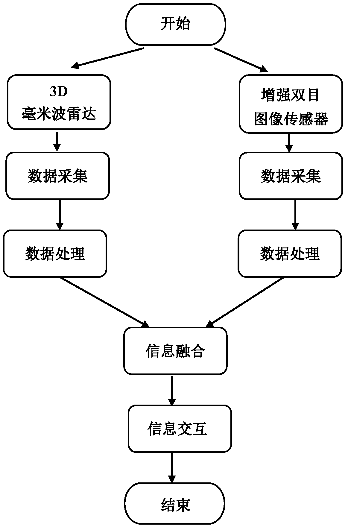
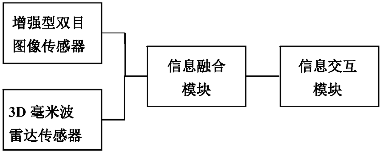
[0037] The present invention proposes a wearable obstacle avoidance device based on an enhanced binocular image sensor and a 3D millimeter-wave radar, aiming to help visually impaired people avoid existing obstacles. The enhanced binocular image sensor and 3D millimeter-wave radar system are organically combined to improve the stability and robustness of the entire system. figure 2 It is a schematic configuration diagram of the device of the present invention, which includes an enhanced binocular image sensor, a low-power 3D millimeter-wave radar, an information fusion module and an information interaction module.

[0038] The basic structure of the enhanced binocular image sensor is as follows image 3 As shown, the image sensor includes an infrared active projector 1; a color camera 2, which receives external signals and outputs spatial color information. When the...


PUM


Abstract

The invention relates to a wearable obstacle avoiding method and device based on an enhanced binocular image sensor and a 3D millimeter wave radar, which belongs to the field of wearable devices. Themethod comprises the steps that 1 the 3D millimeter wave radar and the enhanced binocular image sensor are used to collect the data of the distance, velocity and azimuth of an obstacle; 2 the information collected by the 3D millimeter wave radar and the image sensor are fused; and 3 the fused information of the distance, velocity and azimuth of the obstacle is informed to a device wearer through the information interaction method of sound encoding. The device comprises the image sensor, a radar sensor, an information fusion module and an information interaction module. According to the invention, the method fuses the information of the 3D millimeter wave radar and the enhanced binocular image sensor; the measurement reliability is improved; and the method and device can better help peoplewith vision disabilities to avoid existing obstacles.

Description

technical field [0001] The invention relates to the field of wearable devices, in particular to a wearable obstacle avoidance method and device based on an enhanced binocular image sensor and a 3D millimeter-wave radar. Background technique [0002] Eyes are the organs that human beings obtain the most external information. People with visual impairments have difficulty coping with obstacles that often appear in daily life. Simple blind canes provide limited help, and often miss detection; guide dogs require years of professional training, and are not allowed to enter in some occasions; bionic eye implants are traumatic to the human body and expensive. The fee is not suitable for ordinary visually impaired people. The traditional electronic vision aids mainly include binocular vision aid system, active optical depth camera aid system, laser ranging system and so on. [0003] The visual aid technology based on the binocular camera can provide a certain range of depth images...

Claims


Application Information

Patent Timeline
Patent Type & Authority Applications(China)
IPC IPC(8): G01S13/93H04B7/0413H04N5/247H04N5/33H04N23/90
CPCH04B7/0413H04N5/33G01S13/93H04N23/90
Inventor 龙宁波汪凯巍程瑞琦杨恺伦胡伟健
Owner ZHEJIANG UNIV
Learn More