
Automatic teaching demonstration device

A demonstration device and automatic technology, applied in the field of teaching demonstration, can solve the problems of insufficient design of scientific principle demonstration, time-consuming and laborious, unsuitable for exhibition hall display, etc., and achieve the effect of improving effect, good effect and ingenious design

Pending Publication Date: 2018-10-19
上海市静安区少年宫
View PDF0 Cites 0 Cited by
  • Summary
  • Abstract
  • Description
  • Claims
  • Application Information

AI Technical Summary

Problems solved by technology

It is time-consuming and labor-intensive, so it is not suitable for showroom display
In addition, the existing Gothenburg device pays more attention to fun, and is insufficiently designed in the demonstration of scientific principles

Method used


Image

  • Automatic teaching demonstration device
  • Automatic teaching demonstration device
  • Automatic teaching demonstration device

Examples


Embodiment 1

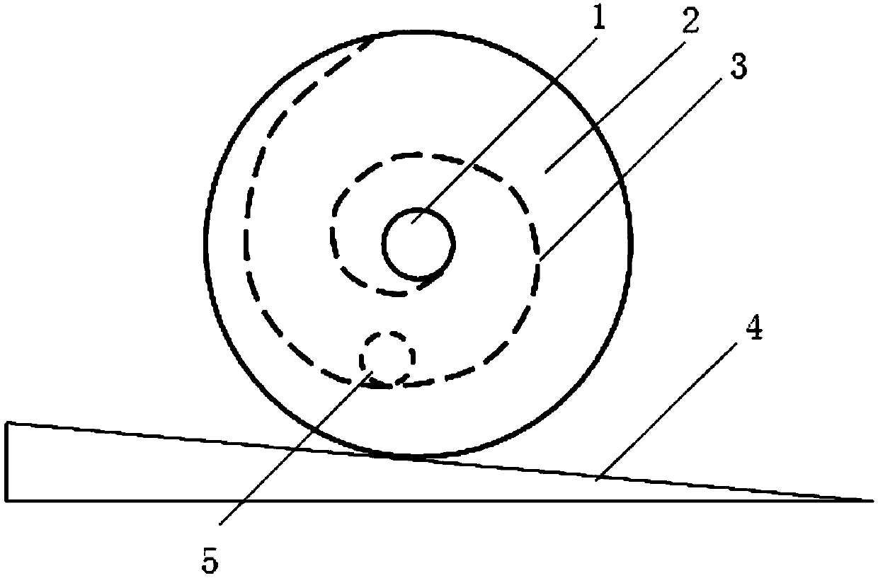
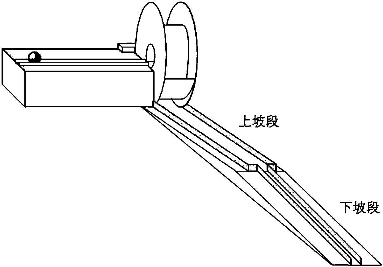
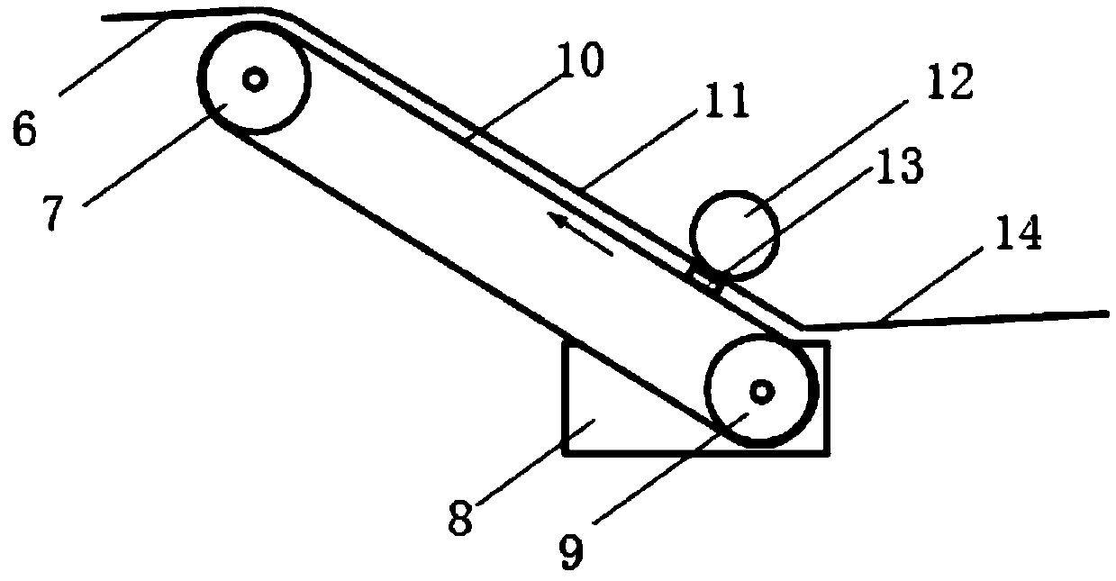
[0023] see Figure 1-Figure 3 , an automatic teaching demonstration device, comprising iron balls, end-to-end closed track; the track has an energy storage lifting section and an energy release falling section; the energy release falling section has a slope 4, and the slope 4 has a rolling The drum has a spiral track inside, and the center of the side wall of the spiral track has a middle hole 1. The position of the middle hole 1 is opposite to the position where the iron ball falls. After the iron ball enters the middle hole, it moves along the spiral track under the action of gravity Rolling inside drives the roller to roll upwards along the slope 4. During this period, the physical center of gravity of the iron ball and the roller as a whole drops; the front section of the slope 4 is an uphill section, and the back section is a downhill section. When the iron ball leaves the roller at the end of the spiral track, Just entering the downhill section, at this time, the roller ...

Embodiment 2

[0034] The difference from the first embodiment is that the side plates 2 on both sides of the drum are made of a material with adjustable transparency.

[0035] The present invention lifts the stored energy through the lifting section of the energy storage, and releases the energy through the falling section of the energy release section, so that it can run reciprocatingly without stopping; it can perform interesting demonstrations of physical principles such as the conversion between potential energy and kinetic energy, and automatically The effect of teaching demonstration is good; it is easy to arouse people's curiosity and entertaining; the drum and its inner spiral track are designed cleverly, and the drum is equipped with transparent side panels and opaque cover plates, which is conducive to improving the effect of teaching demonstration .


PUM


Abstract

The invention relates to an automatic teaching demonstration device. The automatic teaching demonstration device comprises an iron ball and an end-to-end closed rail, wherein the rail is provided withan energy storage lifting section and an energy release falling section; the energy release falling section has a slope with rollers rolling along the slope; the inside of the roller has a spiral rail with a central hole in the side wall of the spiral rail; the position of the central hole faces toward the position where the iron ball falls; after entering the central hole, the iron ball rolls along the spiral rail under the action of gravity to drive the roller to roll up the slope, and during this period, the physical center of gravity of the iron ball and the roller falls as a whole; and the energy storage lifting section drives the iron ball to move upwards to improve the energy release of the iron ball. The automatic teaching demonstration device provided by the invention can alwaysreciprocate without stopping, can give a good interesting demonstration of the physical principles such as the transformation between potential energy and kinetic energy, is easy to arouse people's curiosity and combine education with pleasure, and is ingenious in design of the roller and the spiral rail inside the roller.

Description

technical field [0001] The invention relates to an automatic teaching demonstration device, which belongs to the technical field of teaching demonstration. Background technique [0002] The Gothenburg device is a sophisticated and complex piece of machinery that uses twists and turns to accomplish some very simple tasks, and is popular for its playfulness. The Gothenburg device can be designed with multiple links, and each link contains various simple mechanical principles, such as levers, pulleys, collisions, etc. Through continuous motion transmission, the action of the next link is continuously triggered, and a certain job is finally completed. [0003] Most of the existing Gothenburg installations are disposable. After each demonstration, it is a "ruin". If you want to demonstrate again, you have to rebuild and reset. It is time-consuming and labor-intensive, so it is not suitable for exhibition hall display. In addition, the existing Gothenburg device pays more atten...

Claims


Application Information

Patent Timeline
Patent Type & Authority Applications(China)
IPC IPC(8): G09B23/10
CPCG09B23/10
Inventor 付晓波
Owner 上海市静安区少年宫
Learn More