Steel frame shear wall structure
A steel frame and shear wall technology, applied in the direction of walls, building components, building structures, etc., can solve the problems of complex on-site construction, low construction efficiency, and difficulty in guaranteeing construction quality, and achieve convenient and simple installation and operation, and reduce welding operations , High construction efficiency
- Summary
- Abstract
- Description
- Claims
- Application Information
AI Technical Summary
Problems solved by technology
Method used
Image

Examples
Embodiment 1
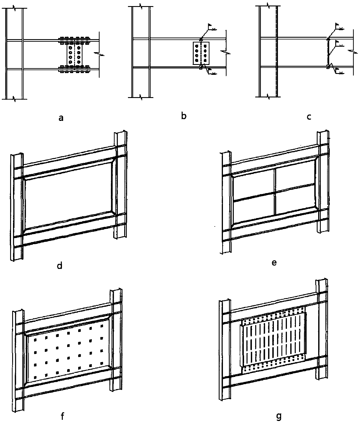
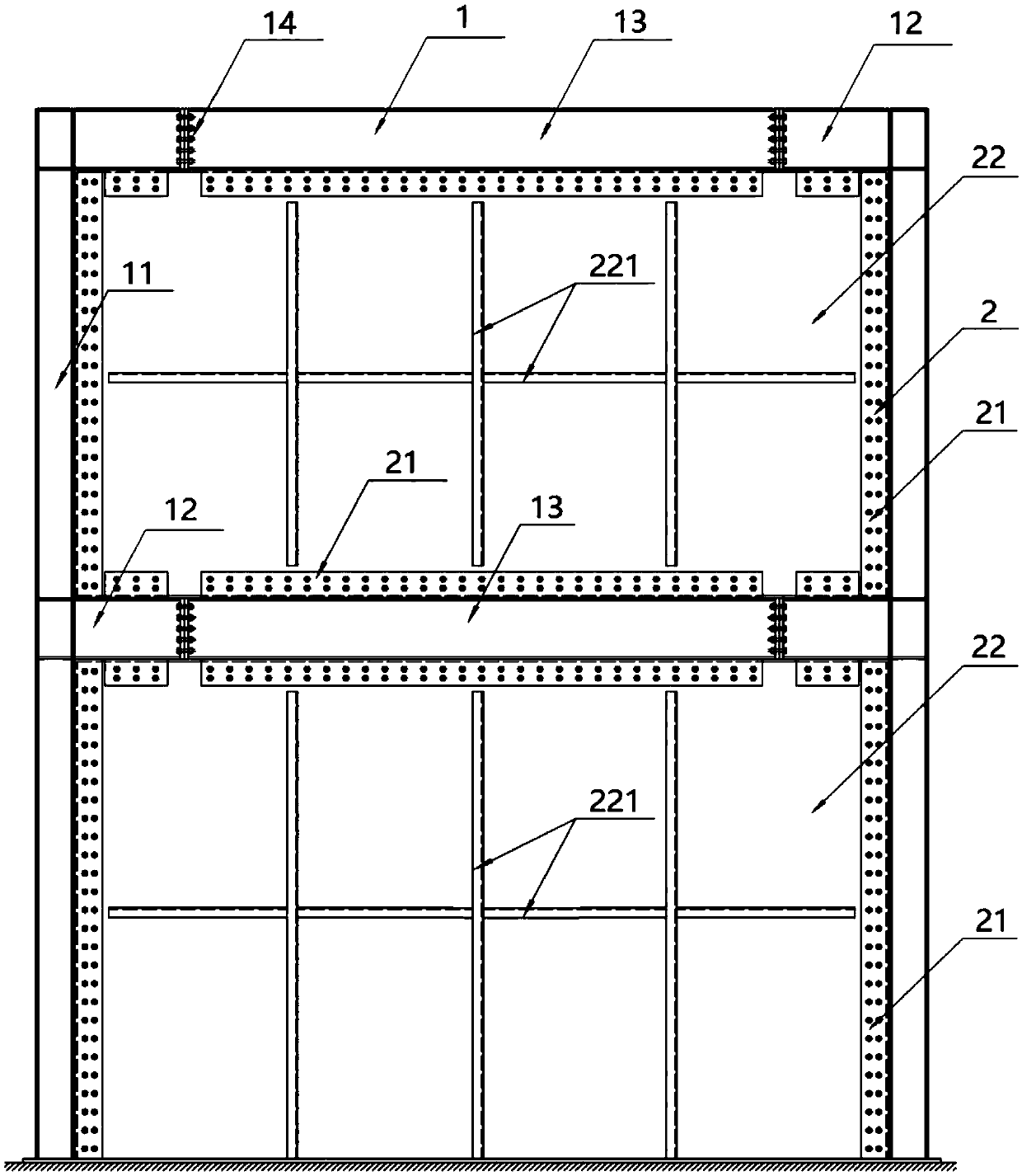
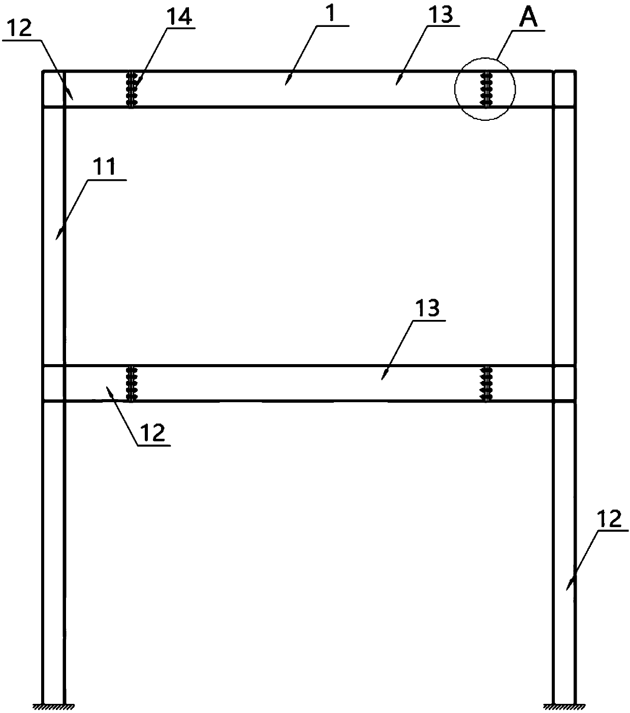
[0040] In this example, if Figure 2-8 As shown, the steel frame shear wall structure includes: a steel frame structure 1 and a wall panel assembly 2 , and the steel frame structure 1 includes: supporting columns 11 , end beams 12 , beams 13 and beam splicing structures 14 .
[0041]The support columns 11 are provided with multiple and vertically arranged, and each support column 11 is provided with a plurality of end beams 12, and the plurality of end beams 12 on each support column 11 are along the center line of the support column 11 The extension direction is arranged at intervals, the end beams 12 are perpendicular to the support columns 11, and the corresponding end beams 12 on the two support columns 11 are arranged oppositely, the cross beams 13 are arranged between the end beams 12, and the first ends of the cross beams 13 are connected On one of the end beams 12 corresponding to the two support columns 11, the second end of the cross beam 13 is connected on the other...
Embodiment 2
[0050] The difference between the steel frame shear wall structure in this embodiment and the first embodiment is that the surface of the first end plate 141 is set at a predetermined angle with the center line of the beam 13, and the surface of the second end plate 142 is set at a predetermined angle with the end Beam 12
[0051] The central line of the center line is set at a predetermined angle, and the first end plate 141 and the second end plate 142 are matched.
[0052] preferred, such as Figure 9 As shown, the angle between the plate surface of the first end plate 141 and the center line of the cross beam 13 is set to 45°, so that the beam splicing structure 14 at both ends of the cross beam 13 is in an inverted figure-eight shape, and the cross beam 13 is subjected to a vertical downward force , in the beam splicing structure 14, the first connecting bolts will be subjected to a shear force along the direction of the first end plate 141 facing downward, and the secon...
Embodiment 3
[0055] The difference between the steel frame shear wall structure in this embodiment and Embodiment 1 is that, as Figure 11 As shown, the fishplate 21 adopts angle steel profiles, and the crossbeam 13, the end beam 12 and the supporting column 11 are welded and fixed with corresponding fishplates 21, and the fishplate 21 is welded through one side plate, and the other side of the fishplate 21 A second bolt hole is opened at the corresponding position of the side plate and the wall plate 22, and the second connecting bolt assembly 23 is penetrated in the second bolt hole to fix the wall plate 22 and the fish plate 21, and the welding of the fish plate 21 The work is prefabricated in the factory. Using angle steel profiles as the fishplate 21 can ensure that the connection between the fishplate 21 and the beam 13, the end beam 12 and the support column 11 is more firm and tight, making the steel frame shear wall structure safer and more reliable.
PUM
 Abstract
Description
Claims
Application Information
 - Generate Ideas
- Intellectual Property
- Life Sciences
- Materials
- Tech Scout
- Unparalleled Data Quality
- Higher Quality Content
- 60% Fewer Hallucinations
Browse by: Latest US Patents, China's latest patents, Technical Efficacy Thesaurus, Application Domain, Technology Topic, Popular Technical Reports.
© 2025 PatSnap. All rights reserved.Legal|Privacy policy|Modern Slavery Act Transparency Statement|Sitemap|About US| Contact US: help@patsnap.com