Clamping tool for workpiece laser processing

A technology of laser processing and clamping tooling, which is applied in the direction of metal material coating process and coating, which can solve the problems of inconvenient angle adjustment and clamping, unfavorable laser processing, etc., achieve good clamping effect and facilitate laser cladding processing , Conducive to the effect of laser cladding processing

Active Publication Date: 2018-10-19
WENZHOU UNIVERSITY
View PDF3 Cites 0 Cited by
  • Summary
  • Abstract
  • Description
  • Claims
  • Application Information

AI Technical Summary

Problems solved by technology

[0005] The purpose of the present invention is to provide a clamping tool for laser processing of workpieces to solve the problems that it is inconvenient to adjust the angle and clamping is not conducive to laser processing during the laser cladding process.

Method used


Image

  • Clamping tool for workpiece laser processing

Examples


Embodiment Construction

[0031] The present invention will be described in further detail below by means of specific embodiments:

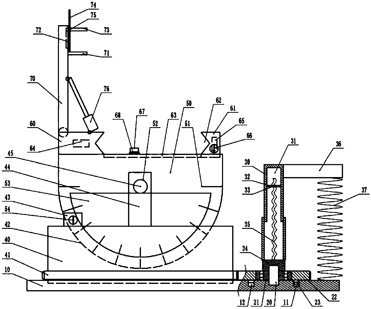
[0032]The reference signs in the drawings of the description include: bottom plate 10, circular groove 11, ratchet 12, short shaft 20, one-way bearing 21, gear 22, teeth 23, telescopic rod 30, inner cavity 31, fixed sleeve 32, Rectangular hole 33, rotary sleeve 34, spiral strip 35, support block 36, elastic member 37, turntable 40, ring gear 41, groove 42, first electromagnet 43, bracket 44, transverse shaft 45, rotary block 50, scale 51. Through hole 52, first magnetic block 53, first switch 54, clamping block 60, moving block 61, clamping groove 62, chute 63, second magnetic block 64, second electromagnet 65, second switch 66. Vibrator 67, elastic support 68, support plate 70, first splint 71, dovetail groove 72, second splint 73, screw rod 74, screw hole 75, cylinder 76.

[0033] Such as figure 1 As shown, the clamping tool for workpiece laser processing includes a b...


PUM


Abstract

The invention belongs to the technical field of laser processing tools, and particularly discloses a clamping tool for workpiece laser processing. The clamping tool comprises a bottom plate and a telescopic rod. A rotary table is rotationally connected to the bottom plate. A gear ring is arranged on the outer portion of the rotary table. A short shaft is rotationally arranged on the bottom plate.A unilateral bearing is arranged outside the short shaft. A gear engaged with the gear ring is fixed outside the unilateral bearing. A rotating sleeve is rotationally arranged at the lower end of thetelescopic rod. An inner cavity is arranged in the telescopic rod. A spiral strip stretching into the inner cavity is arranged in the center of the rotating sleeve, wherein the cross section of the spiral strip is rectangular. A fixed sleeve is arranged in the middle of the inner cavity. A rectangular hole in sliding fit with the spiral strip is formed in the center of the fixed sleeve. The lowerend of the rotating sleeve is fixedly connected with the short shaft. A supporting block is arranged at the upper end of the telescopic rod. An elastic part for supporting the telescopic rod is arranged between the bottom plate and the supporting block. Compared with the prior art, the tool can clamp workpieces well, and after clamping, the positions and angles of the workpieces can be adjusted according to the requirements of laser processing.

Description

technical field [0001] The invention belongs to the technical field of laser processing tools, and specifically discloses a clamping tool for workpiece laser processing. Background technique [0002] Laser processing is the fastest growing, most widely used and most promising field of laser application technology. At present, there are more than 20 kinds of laser processing technologies developed, such as laser welding, laser cutting, laser rapid prototyping, laser Repair, etc. These laser processing technologies have been widely used in machinery, electronics, automobiles and other industries. Compared with traditional mechanical processing methods, laser processing has incomparable advantages. Laser processing has high processing precision, fast speed, and small mechanical deformation. , material saving, good flexibility, wide processing range, etc. At the same time, laser processing is easy to combine with computer-aided design / computer-aided manufacturing, which is conve...

Claims


Application Information

Patent Timeline
Patent Type & Authority Applications(China)
IPC IPC(8): C23C24/10
CPCC23C24/10
Inventor 谢小文
Owner WENZHOU UNIVERSITY
Why Eureka
Try Eureka