Robot path planning method and system based on topology map
A path planning and topology map technology, applied in control/regulation systems, instruments, vehicles, etc., can solve problems such as increasing the complexity of the algorithm, limiting the search space, etc., to avoid the effect of expressing too high time and space complexity
- Summary
- Abstract
- Description
- Claims
- Application Information
AI Technical Summary
Problems solved by technology
Method used
Image
Examples
specific Embodiment 1
[0073] figure 1 It is a flowchart of a robot path planning method based on a topology map according to an embodiment of the present invention. Such as figure 1 Shown, a kind of robot path planning method based on topological map, described method comprises:
[0074] Step 101: Obtain a scatter diagram, and set the initial movement point and target point of the robot in the scatter diagram, the scatter diagram is abstracted from the actual environment containing obstacle nodes;
[0075] Step 102: Constructing a Voronoi diagram corresponding to the scatter diagram according to the scatter diagram;
[0076] Specifically comprising, sequentially connecting the three closest obstacle nodes in the scatter diagram to obtain a plurality of triangles, the circumcircle of the triangles does not contain other obstacle nodes, and each of the triangles forms a triangular network;
[0077] A vertical line is drawn for each side of the triangular network to obtain a grid diagram formed by ...
specific Embodiment 2
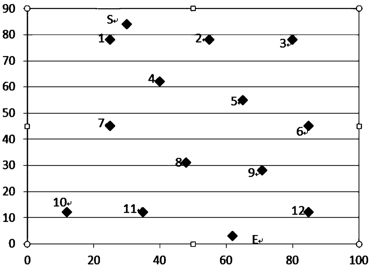
[0125] Step 1: System initialization. The actual environment containing obstacles is abstracted into a scatter diagram, and the generated scatter diagram is as follows image 3 shown. Among them, the obstacle points are respectively marked as 1, 2, 3..11, 12, the starting point of the robot is marked as S, and the end point of the robot is marked as E.
[0126] Step 2: Build image 3 The Voronoi diagram corresponding to the scatter diagram in the middle, specifically includes:
[0127] ① Connect sequentially image 3 The three closest obstacle points in the scatter diagram require that the triangle obtained each time does not contain other obstacle points in its circumscribed circle, thus obtaining the Delaunay triangulation, such as Figure 4 shown by the black line.
[0128] ② Draw a vertical line for each side of the constructed Delaunay triangulation, and the grid formed by the intersection of all the vertical lines is a Voronoi diagram, as shown in Figure 4 shown b...
PUM
 Abstract
Description
Claims
Application Information
 - R&D Engineer
- R&D Manager
- IP Professional
- Industry Leading Data Capabilities
- Powerful AI technology
- Patent DNA Extraction
Browse by: Latest US Patents, China's latest patents, Technical Efficacy Thesaurus, Application Domain, Technology Topic, Popular Technical Reports.
© 2024 PatSnap. All rights reserved.Legal|Privacy policy|Modern Slavery Act Transparency Statement|Sitemap|About US| Contact US: help@patsnap.com


