
A non-inflatable air spacer

An air-spaced, non-inflatable technology, applied in blasting and other directions, can solve the problems of high gas expansion speed and operating requirements of operators, slow expansion speed of spacers, affecting field operation efficiency, etc., to improve blasting effect and promote uniform crushing. , the effect of high work efficiency

Active Publication Date: 2019-12-03
CHINA GEZHOUBA GRP YIPULI CO LTD
View PDF5 Cites 0 Cited by
  • Summary
  • Abstract
  • Description
  • Claims
  • Application Information

AI Technical Summary

Problems solved by technology

In addition, the expansion time of the gas is extremely sensitive to the weather. It takes a long time to expand to meet the strength requirements in winter, which directly affects the efficiency of on-site operations.
For spacer charging under water hole conditions, although the pull-type spacer can also meet the construction requirements, it has higher requirements on the gas expansion speed and the operator's operation. If the spacer expansion speed is too slow or the operation is not in place, it is easy to cause the spacer Bloating occurs in water, while the other two spacers are not suitable for use in water hole conditions
In addition, the air spacer under traditional conditions only simply separates the explosives, and the energy of the explosives directly acts on the blocked section of the orifice, which is prone to punching

Method used


Image

  • A non-inflatable air spacer
  • A non-inflatable air spacer
  • A non-inflatable air spacer

Examples


Embodiment Construction

[0022] The present invention will be further described below in conjunction with the accompanying drawings. The embodiments are exemplary and are only used to disclose and explain the present invention so as to fully understand the present invention, but the present invention is not therefore limited within the scope of the described embodiments. .

[0023] It should be noted that, unless otherwise specified and limited, in the description of the present invention, the terms "installation", "connection" and "connection" should be understood in a broad sense, for example, it can be mechanical connection or electrical connection, or two The internal communication of each element may be directly connected or indirectly connected through an intermediary. Those skilled in the art can understand the specific meanings of the above terms according to specific situations.

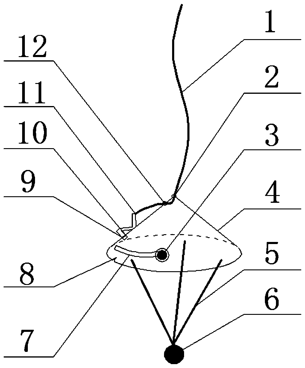
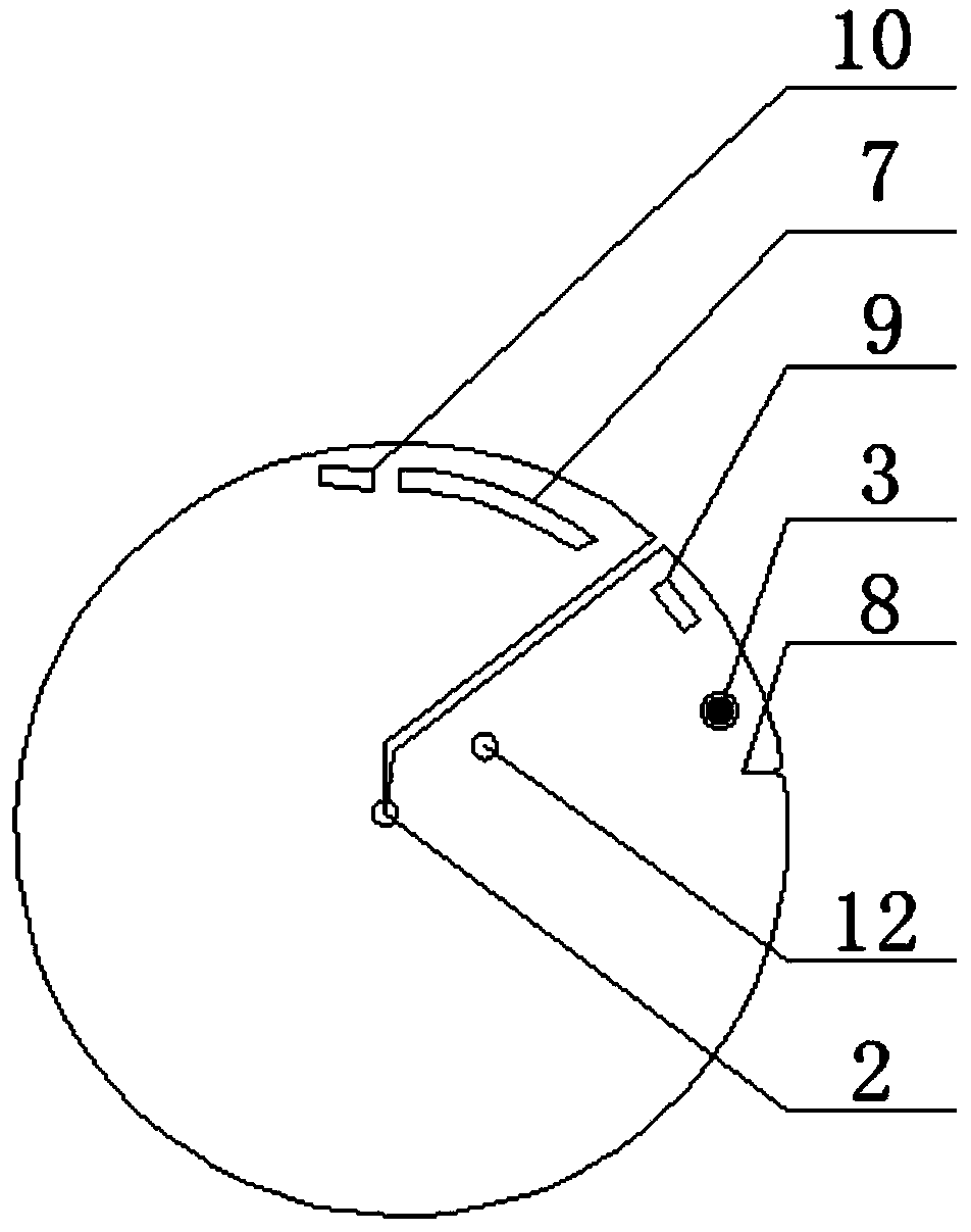
[0024] Such as figure 1 A non-inflatable air spacer is shown, including an energy gathering shell 4, a scale rop...


PUM


Abstract

The invention relates to a non-inflation air spacer. The non-inflation air spacer comprises an elastic-deformed conical energy collecting shell; the energy collecting shell forms an inner and outer layer overlap structure at a joint part; inner and outer layers are clamped and fixed with one end of a buckle through a clamping groove; the buckle forms a prying bar structure through middle butting;the clamped end of the buckle is deviated from the clamping groove through triggering of the other end of the prying bar; the energy collecting shell is fixedly connected with a scale rope through a rope clamping port at a large end; an inner section of the scale rope is inserted in and out in sequence from a first through hole and a second through hole at the top and the upper part of the energycollecting shell; an inner end, penetrating out of the second through hole, of the scale rope is fixed at the other end of the buckle; and the energy collecting shell is connected with a counterweightthrough a fixed rope. The non-inflation air spacer has the following beneficial effects: an air spacing construction method can be realized without inflating; no influence is from weather conditionsand dry and wet environments; and a conical energy collecting cavity with a downward tip can guarantee the bombing energy to be mainly acted on the hole walls to promote uniform crushing of rocks on the hole orifices and the hole walls, so that the punching phenomenon is reduced, and the blasting effect is improved.

Description

technical field [0001] The invention relates to a spacer for explosive-interval charging, in particular to a non-inflatable air spacer suitable for explosive-interval charge in open-pit mines. Background technique [0002] Air-spaced charge is more and more widely used in step blasting in open-pit mines. It can effectively reduce the amount of single-hole explosive, balance energy distribution, and prolong the action time of detonation gas, thereby improving the blasting effect. According to different structures, it can be divided into bottom air-spaced charge, middle air-spaced charge and upper air-spaced charge. In the traditional mode, the spacers used for air-spaced charges mainly include three types: push type, pull type and inflatable type, but these three methods all use the structural principle of the inflatable type to form the air bag to squeeze the wall of the blast hole, and all of them have their limitations. For example, the gas used for inflation must be an ...

Claims


Application Information

Patent Timeline
Patent Type & Authority Patents(China)
IPC IPC(8): F42D1/00F42D3/04
CPCF42D1/00F42D3/04
Inventor 朱宽郝亚飞曹进军
Owner CHINA GEZHOUBA GRP YIPULI CO LTD
Learn More