
Sewing machine

A technology for sewing machines and the first thread, which is applied to sewing machine components, sewing equipment, and mechanisms for cutting threads in sewing machines. It can solve problems such as increased frequency of lubricating oil replenishment and increased man-hours for cleaning the bottom cover, etc., to reduce lubricating oil The effect of the leak

Active Publication Date: 2018-10-09
JUKI CORP
View PDF9 Cites 0 Cited by
  • Summary
  • Abstract
  • Description
  • Claims
  • Application Information

AI Technical Summary

Problems solved by technology

[0006] Therefore, the lubricating oil scattered inside the sewing machine arm passes through the thread member due to capillary phenomenon, and the lubricating oil reaches the thread cutting solenoid and drips to the bottom cover arranged under the base. Increased working hours and increased frequency of lubricating oil replenishment

Method used


Image

  • Sewing machine
  • Sewing machine

Examples


Embodiment Construction

[0052] [Schematic structure of the embodiment]

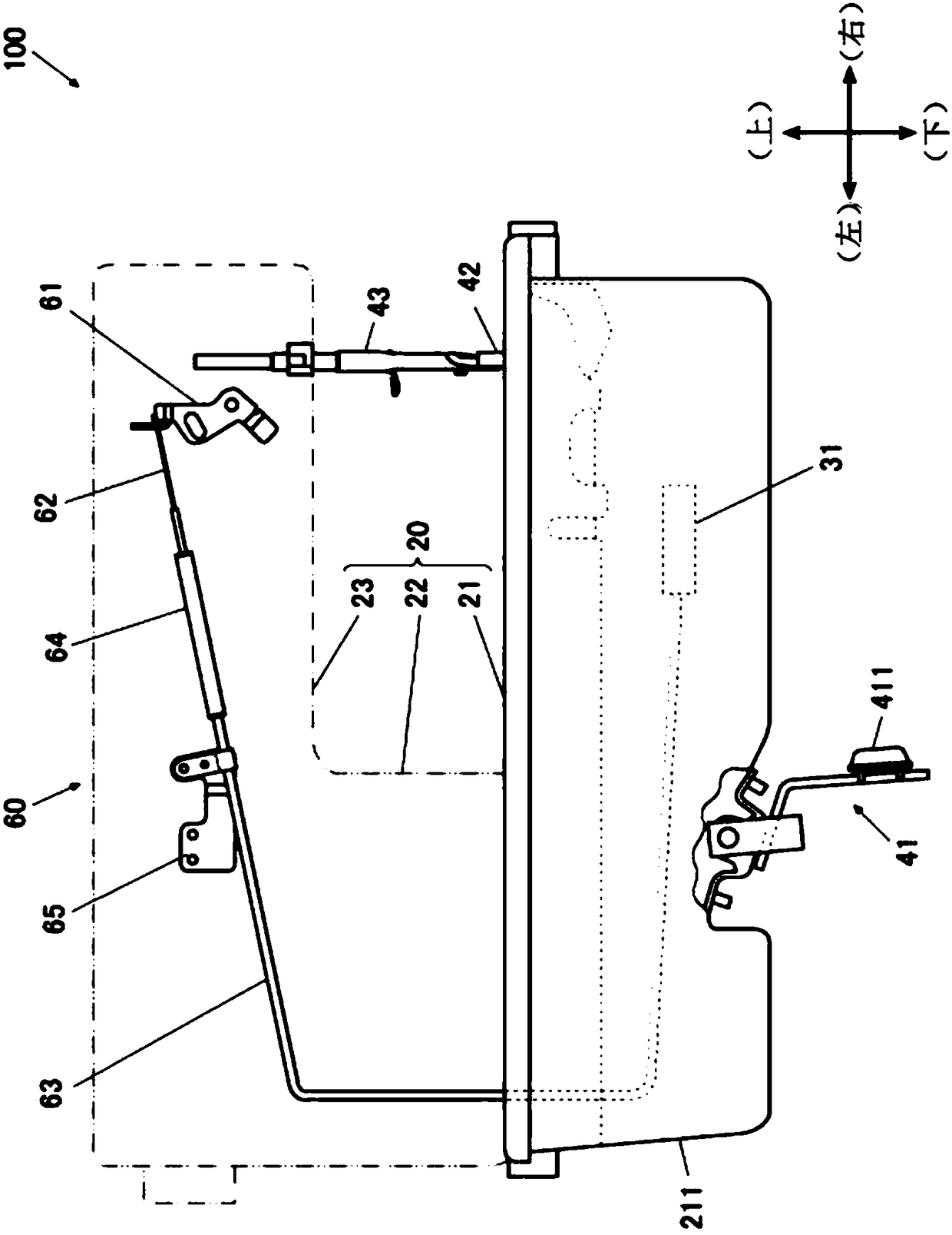
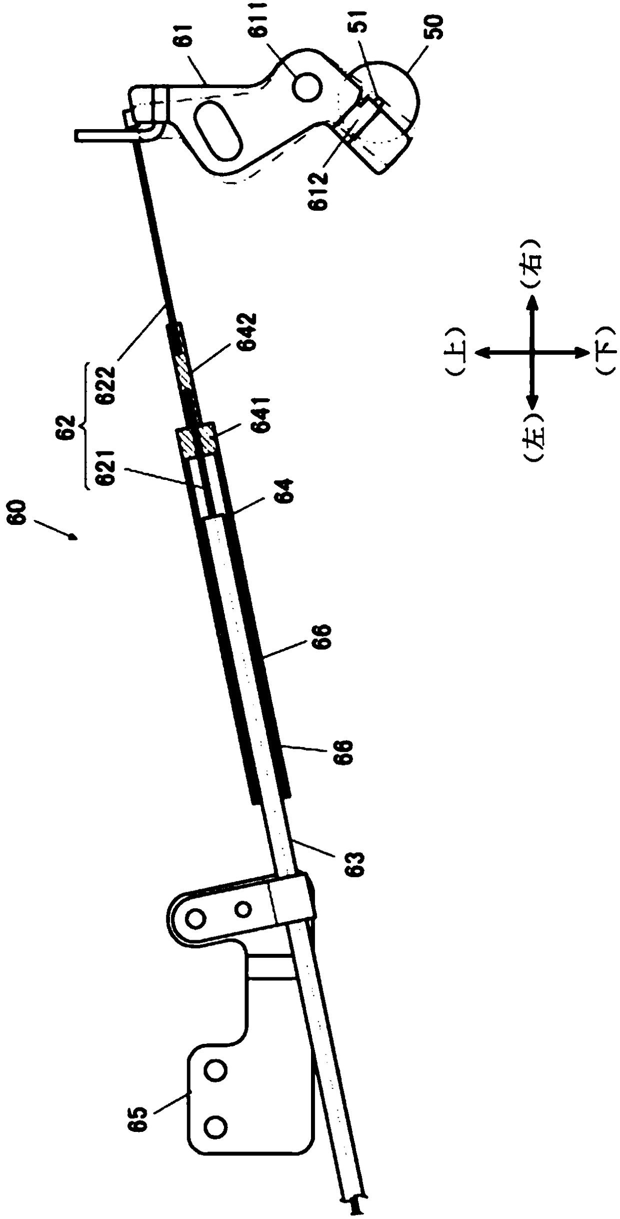
[0053] Below, based on figure 1 and figure 2 , the sewing machine which is an embodiment of the present invention will be described in detail.

[0054] figure 1 is a schematic view of the sewing machine 100 viewed from the side opposite to the sewing machine user's side, figure 2 It is an enlarged view showing a part of the structure in the arm of the sewing machine in partial cross-section.

[0055] In addition, in the following description, the sewing machine user side of the sewing machine 100 ( figure 1 The back side of the paper surface) is set as the front side, and the side opposite to the user side ( figure 1 The paper surface side) is set as the rear side, and the sewing machine upright body part 22 side described later ( figure 1 left in ) as the left side, set the needle bar side ( figure 1 The right side in ) is set to the right side.

[0056] The sewing machine 100 according to the embodiment of the presen...


PUM


Abstract

The invention relates to a sewing machine, being able to restrain leakage of lubricating oil. The sewing machine is provided with a linkage thread (62). The linkage thread (62) connects an actuator (31) that performs thread cutting of a thread cutting device and a thread release member (51) that switches the thread tension applying state of a thread adjusting device (5) to a release state. The linkage line is formed by a first thread (621) and a second thread (622), wherein one end of the first thread is coupled to a coupling member (64), and the other end is coupled to the actuator; one end of the second thread is coupled to the thread release member, and the other end is coupled to a coupling member; and the coupling member is configured to block penetration of the lubricating oil due tothe capillary phenomenon from any one of the first thread and the second thread to the other.

Description

technical field [0001] The present invention relates to a sewing machine with a thread release mechanism. Background technique [0002] In the existing sewing machine, in order to link the thread cutting and the release of the thread tension applied state by the thread regulator device, the plunger of the thread trimming solenoid that performs thread trimming and the release plate of the thread regulator device are used to connect the outer tube The inserted wire member (Wire) is connected, and the tension of the wire member is used to rotate the loosening plate by driving the plunger to activate the tension release lever of the wire adjuster device (for example, refer to Patent Document 1). [0003] Patent Document 1: Japanese Unexamined Patent Publication No. 2013-212171 [0004] In addition, in order to prevent the leakage of lubricating oil in recent sewing machines, a gear box is installed on the base of the sewing machine, and a gear for transmitting the power of the ...

Claims


Application Information

Patent Timeline
IPC IPC(8): D05B71/00D05B65/00D05B29/02
CPCD05B29/02D05B65/00D05B71/00
Inventor 加藤修平岩田寿之小川达矢
Owner JUKI CORP
Learn More