
cotton thread production equipment

A technology for production equipment and cotton thread, applied in textiles and papermaking, fiber processing, deburring devices, etc., can solve the problem of high replacement costs, achieve the effects of saving replacement costs, simple operation, and eliminating potential safety hazards

Inactive Publication Date: 2019-09-13
NANTONG DOUBLE GREAT TEXTILE
View PDF9 Cites 0 Cited by
  • Summary
  • Abstract
  • Description
  • Claims
  • Application Information

AI Technical Summary

Problems solved by technology

[0003] The present invention intends to provide a cotton thread production equipment to solve the problem that the licker-in rollers in the existing carding machines need to be replaced as a whole after a period of use, resulting in high replacement costs

Method used

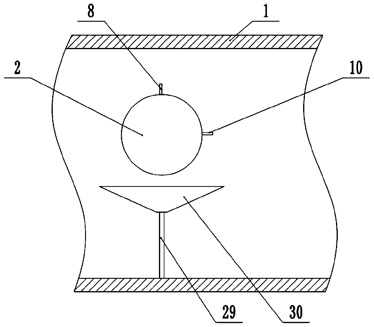
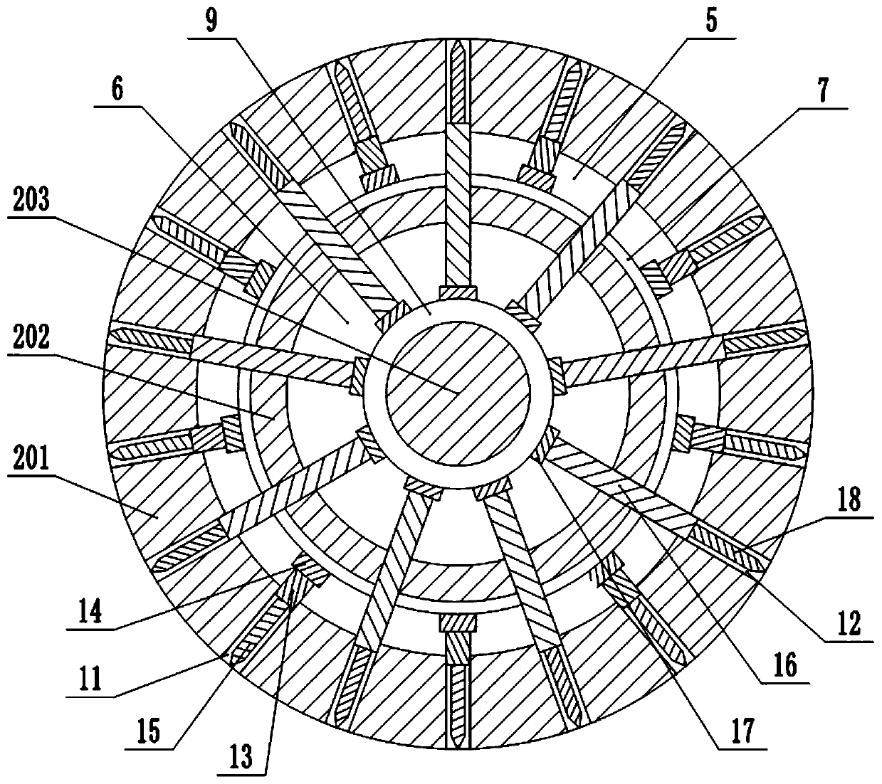
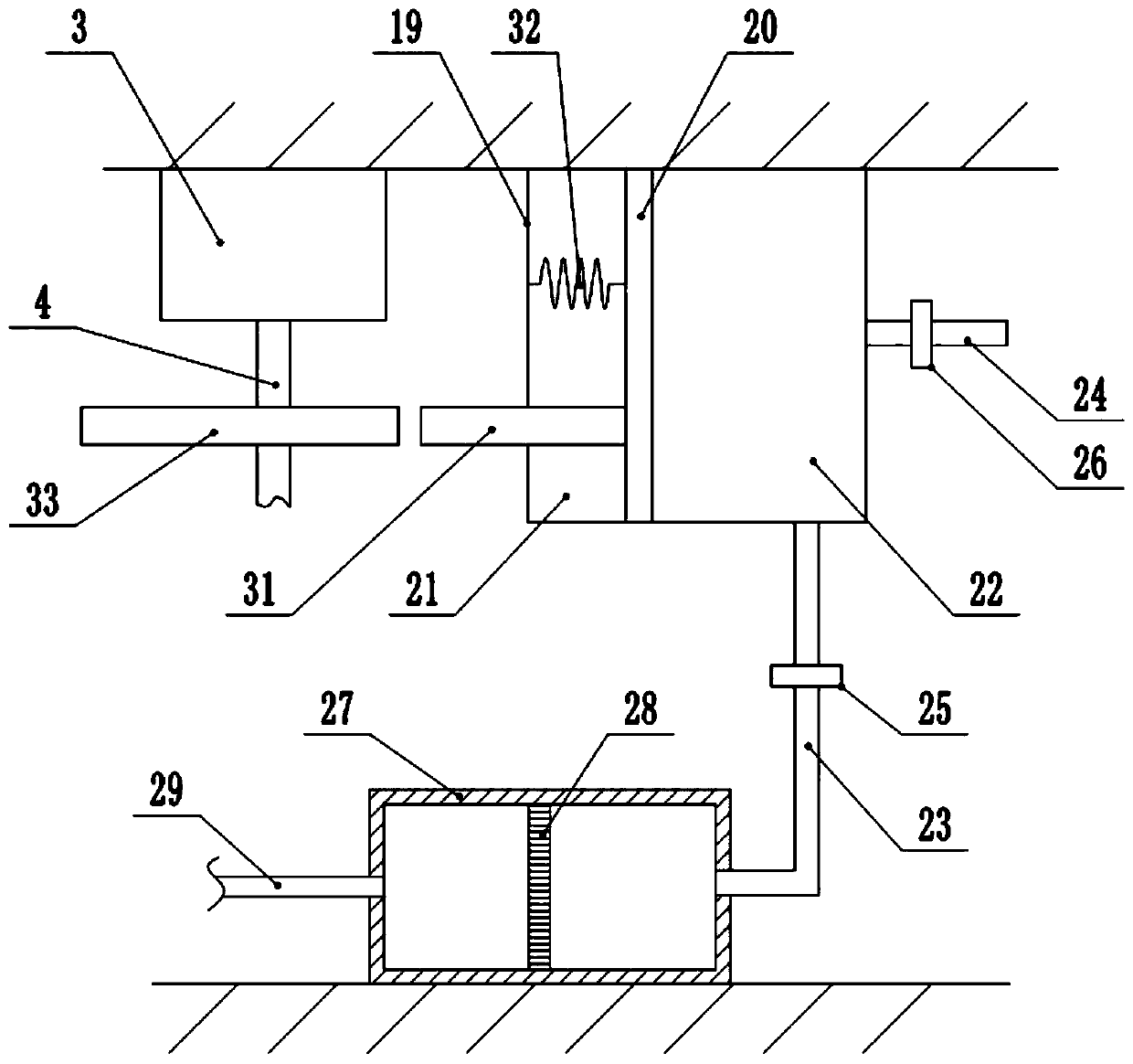

Image

  • cotton thread production equipment
  • cotton thread production equipment
  • cotton thread production equipment

Examples


Embodiment 1

[0028] This embodiment is basically as figure 1 As shown, the cotton thread production equipment includes a carding machine housing 1, a rotating roller 2 and a motor 3 for driving the rotating roller 2, and the rotating roller 2 is connected in rotation on the front and rear side walls of the carding machine housing 1, and the motor The output end of 3 is fixedly connected with rotating shaft 4 coaxially, and rotating shaft 4 is fixedly connected with rotating roller 2 coaxially. combine figure 2 As shown, a first cavity 5 and a second cavity 6 are provided in the rotating roller 2, and the first cavity 5 and the second cavity 6 are all arranged along the circumferential direction of the rotating roller 2, and the first cavity 5 and the second cavity The cavity 6 divides the rotating roller 2 into a first roller body 201 , a second roller body 202 and a third roller body 203 .

[0029] The first elastic airbag 7 is fixedly installed on the inner peripheral wall of the firs...

Embodiment 2

[0039] Such as figure 1 , figure 2 and Figure 4 As shown, the difference from Embodiment 1 is that the top end of the first air outlet pipe 24 is threadedly connected with a second air outlet pipe 34, the upper end of the second air outlet pipe 34 communicates with a third elastic air bag 35, and the third elastic air bag 35 communicates with a Air release pipe 36 and air delivery pipe 37, air pressure valve 38 and the third air valve 39 are installed on the air release pipe 36, the third air valve 39 is in normally open state, the fourth air valve 40 is installed on the air delivery pipe 37, the fourth air valve 40 is in a normally closed state.

[0040] During specific work, the gas in the right chamber 22 is stored in the third elastic air bag 35 through the first air outlet pipe 24 and the second air outlet pipe 34, and when the internal pressure of the third elastic air bag 35 gradually increases to the threshold value of the air pressure valve 38 At this time, the g...


PUM


Abstract

The invention relates to the technical field of textile equipment and particularly discloses a cotton thread production apparatus, comprising a roller; a first cavity and a second cavity are arrangedin the roller; the first cavity and the second cavity divide the roller into a first roller body, a second roller body and a third roller body; an elastic balloon is arranged in each of the first andsecond cavities and is communicated with a vent tube extended out of the roller; each vent tube is fitted with an air valve; a plurality of channels are arranged in each of the first and second rollerbodies and are arranged radially along the roller; push rods are intermittently fitted in each passage; a push plate is fixedly connected to one end of each push rod, and the other end of the push rod is in threaded connection with a piercing needle positioned outside the roller, and the push plates are fixedly connected to the elastic balloons. The cotton thread production apparatus has the advantages that since the piercing needles are in threaded connection with the push rods, part of the piercing needles which are severely abraded can be changed without changing a whole piercing roller, and cost is saved for enterprises.

Description

technical field [0001] The invention relates to the technical field of textile equipment, and specifically discloses a cotton thread production equipment. Background technique [0002] The production process of cotton thread is mainly divided into opening and cleaning process, carding process, sliver coiling process, combing process, drawing process, roving process, spinning process, winding process, and twisting process. The main function of the carding process is For carding, impurity removal, mixing and slivering, the main machine equipment used is carding machine. The carding machine mainly includes three parts: the pre-carding part, the main carding part and the sliver part. The pre-carding part mainly includes components such as licker-in rollers, feeding rollers and feeding boards. The licker-in rollers used in the current carding machines are often fixedly connected with a number of needles on the outer wall of the rotating roller, and the needles and the rotating r...

Claims


Application Information

Patent Timeline
Patent Type & Authority Patents(China)
IPC IPC(8): D01G15/14D01G15/92D01G15/12
Inventor 付兴国毛国权谈小年
Owner NANTONG DOUBLE GREAT TEXTILE
Learn More