
Dual clutch with drive ring optimized for removal

A dual clutch and tool technology, applied in mechanical drive clutches, clutches, friction clutches, etc., can solve the problems of accidental deformation of the driving member, plastic deformation of the annular tooth area, etc., and achieve the effect of reducing the radial size and being easy to manufacture.

Active Publication Date: 2020-07-24
SCHAEFFLER TECH AG & CO KG
View PDF9 Cites 0 Cited by
  • Summary
  • Abstract
  • Description
  • Claims
  • Application Information

AI Technical Summary

Problems solved by technology

[0005] However, it has been shown in double clutches with drive elements (also referred to as drive rings) that in some cases the ring toothing can be damaged due to the removal or push-off forces to be applied by a corresponding assembly or dismounting device. plastic deformation of the area
In addition to this risk of unintentional deformation of the driver component caused by the assembly or disassembly device, there are the following disadvantages when placing the corresponding assembly or disassembly device in a radially outer position of the driver component : There must be provided a sufficiently large free space so that the assembly or disassembly device can be hooked back into the composite structure consisting of the driving element and the central plate

Method used


Image

  • Dual clutch with drive ring optimized for removal
  • Dual clutch with drive ring optimized for removal
  • Dual clutch with drive ring optimized for removal

Examples


Embodiment Construction

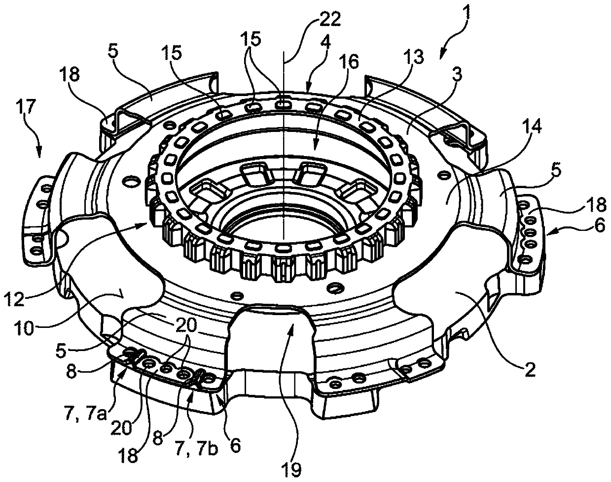
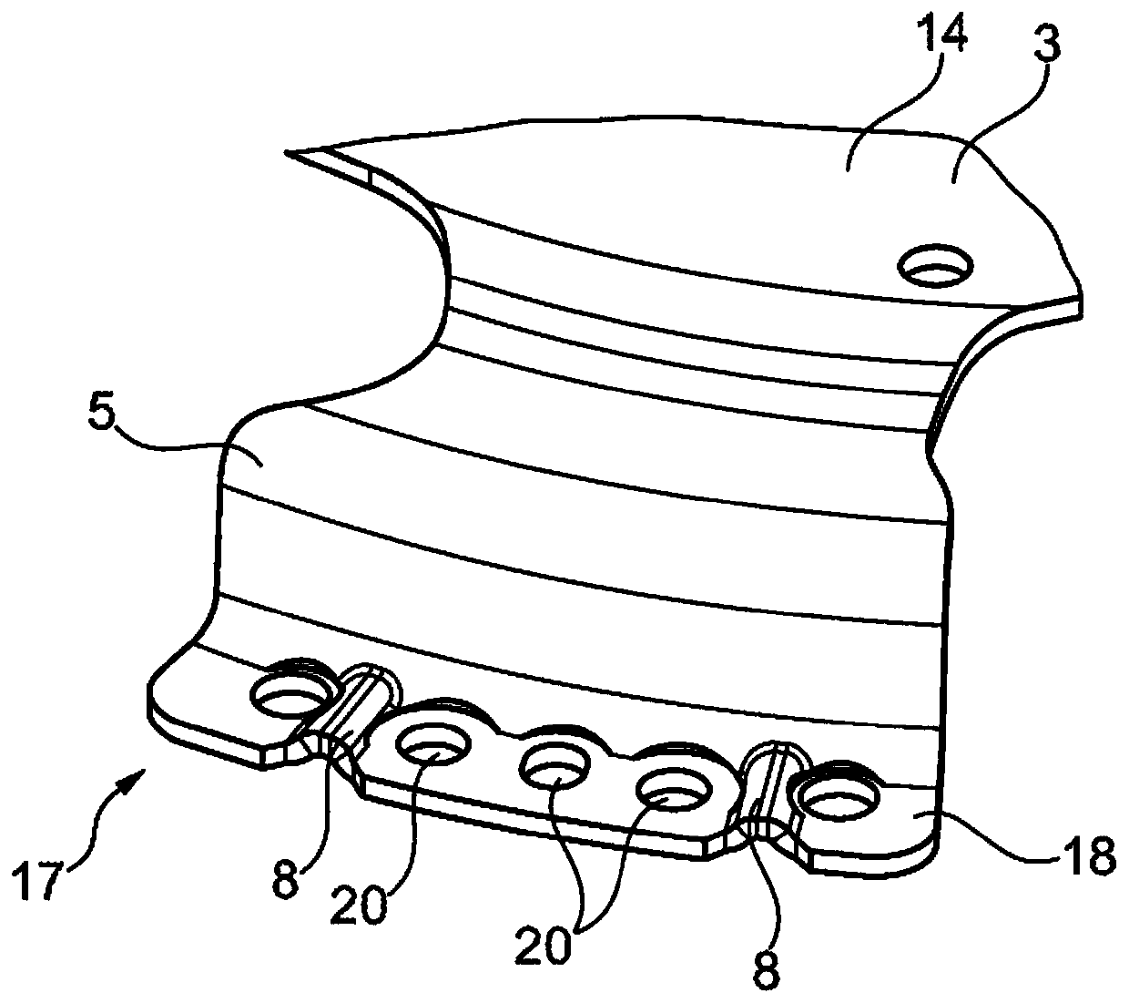
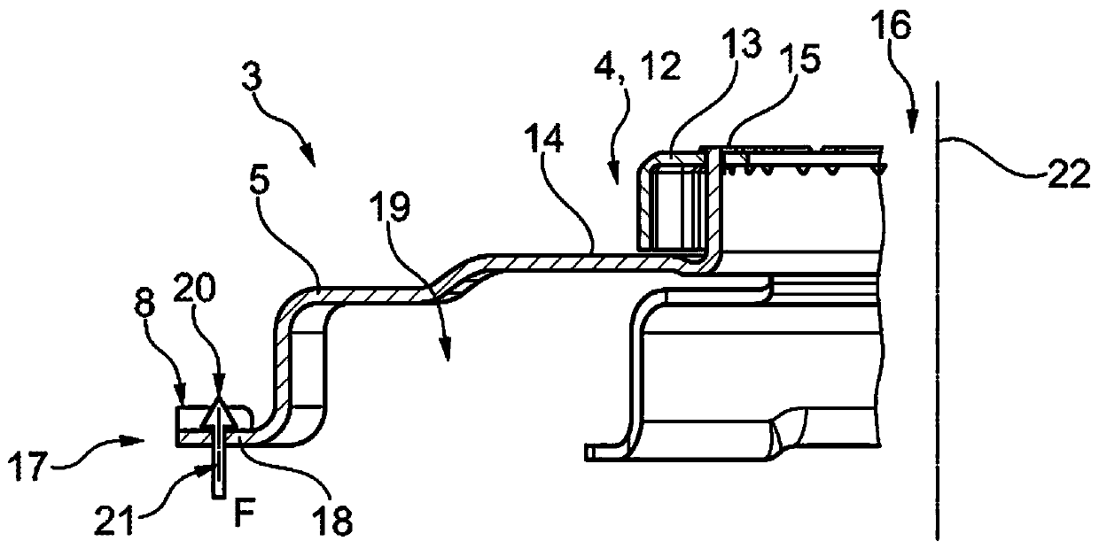
[0029] figure 1 The central plate-entraining member-assembly 1 of the double clutch according to the invention is shown. For the sake of clarity, the dual clutch according to the invention is only shown in the region of the assembly 1, wherein the dual clutch is as far as possible in the usual manner as the known dual clutch, which has been disclosed, for example, by DE 10 2005 037 514 A1 construction and operation. The torque transmission device of DE 10 2005 037 514 A1 is therefore considered to be integrated in this other embodiment of the dual clutch, which is not shown here for the sake of clarity. The dual clutch according to the invention is therefore also conventionally designed as a separable coupling element for a drive train of a motor vehicle and is accommodated during operation in the torque flow between the internal combustion engine and the transmission.

[0030] The shown central plate-entraining component assembly 1 has a central plate 2 and an entraining co...


PUM


Abstract

The invention relates to a double clutch for a drive train of a motor vehicle, having a central plate (2) and a housing-like driver component (3) rotationally fixedly connected to the central plate (2), wherein the driver component (3) as an annularly configured toothed area (4) and a fixing lug (5) arranged radially outside the toothed area (4), which rests on and is fixed to a receiving section (6) of the central plate (2) in the axial direction, wherein at least one tool engagement cavity (7) is configured between the receiving section (6) and the fixing lug (5), which is open toward the outside in the radial direction in order to receive a mounting and / or disassembly tool in a form fitting manner.

Description

technical field [0001] The invention relates to a dual clutch for a drive train of a motor vehicle, such as a passenger car, a truck, a bus or an agricultural commercial vehicle, which has a central plate (also called central counter plate / central pressure plate) and a housing-shaped driving component connected to the central plate in a rotationally fixed manner, wherein the driving component has a ring-shaped (preferably prepared for crankshaft-side connection) toothing area and A fastening web arranged radially outside the toothing region, which abuts and is fastened in the axial direction on the receiving section of the central plate. Background technique [0002] A double clutch of this type is known, for example, from DE 10 2005 037 514 A1. Double clutches, referred to here as torque transfer devices, are in turn used in motor vehicle drive trains. Here, the central pressure plate is supported in the radial direction on a transmission input shaft. [0003] Such a dua...

Claims


Application Information

Patent Timeline
Patent Type & Authority Patents(China)
IPC IPC(8): F16D21/06
CPCF16D13/70F16D21/06F16D2021/0607F16D2300/12
Inventor D·魏斯M·霍佩A·希尔特
Owner SCHAEFFLER TECH AG & CO KG
Learn More