
Intelligent lightning protection system of power transmission line

A lightning protection system and transmission line technology, applied in the field of lightning arresters, can solve the problems of falling, many operation procedures, erosion, etc., and achieve the effects of strong practicability, convenient use and high reliability

Inactive Publication Date: 2018-09-28
海南智弘智能信息化工程有限公司
View PDF6 Cites 3 Cited by
  • Summary
  • Abstract
  • Description
  • Claims
  • Application Information

AI Technical Summary

Problems solved by technology

Because there are many types of iron towers and the cross-arms of overhead ground wires are diversified, the conventional method of installing lightning arresters is to drill holes on the iron towers or cross-arm angle steels, and install connecting plates to connect lightning arresters. Structural strength, and the iron tower is vulnerable to corrosion after the galvanized layer is damaged by drilling
[0003] In order to solve the above problems, someone designed a universal bracket, which connects the angle steel through the bottom plate and clips. The clips are U-shaped or V-shaped structures, and arc-shaped holes are set on the bottom plate to adjust the arrester when the iron tower or cross-arm angle steel is not level. The vertical installation position keeps the arrester vertical and horizontal. However, the adjustment structure of the arc-shaped hole requires the staff to operate at the height of the iron tower or pole, and it needs to be tightened after adjustment. The operation procedures are many and complicated. The prolongation of the use time is easy to be corroded, causing loosening and falling, and the safety is not high.

Method used


Image

  • Intelligent lightning protection system of power transmission line

Examples


Embodiment Construction

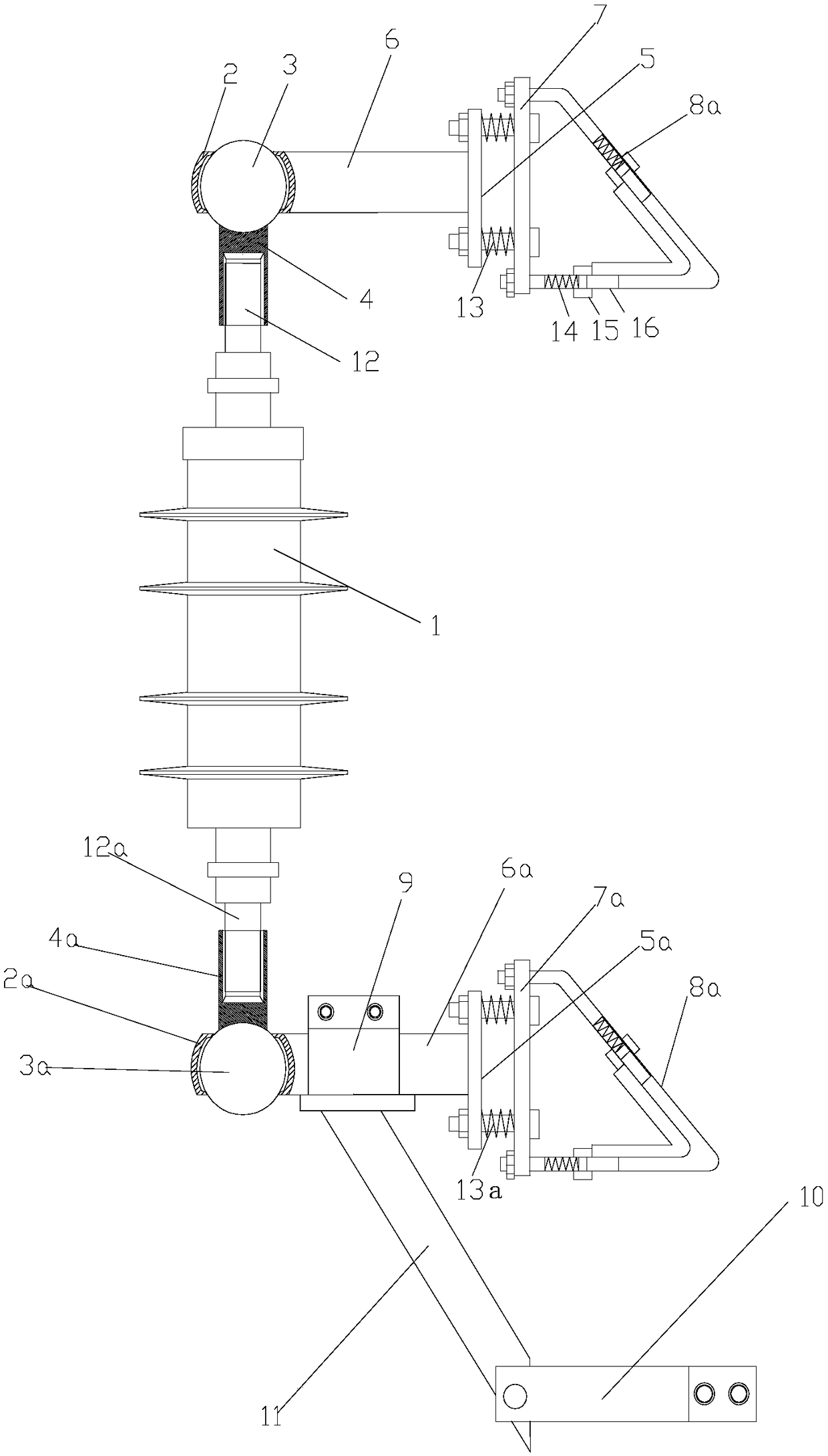
[0014] As shown in the figure: the transmission line intelligent lightning protection system of this embodiment includes a lightning arrester body 1 and an upper connection assembly and a lower connection assembly respectively used to connect the upper and lower ends of the lightning arrester body 1 and the pole cross arm, the upper connection assembly and the lower connection assembly. The components have the same structure, and both at least include an outer ball bag (outer ball bag 2 and outer ball bag 2a in the figure), a sphere movably connected with the outer ball bag (ball 3 and sphere 3a in the figure) and a 1 vertical connecting arm (vertical connecting arm 4 and vertical connecting arm 4a in the figure) with threaded ends, vertical connecting arm 4 is fixedly connected to sphere 3, vertical connecting arm 4a is fixedly connected to sphere 3a, and sphere It can be fixedly connected with the vertical connecting arm by welding, and can also be integrally formed, and the ...


PUM


Abstract

The invention discloses an intelligent lightning protection system of a power transmission line. The intelligent lightning protection system comprises a lightning arrestor body, and an upper connecting assembly and a lower connecting assembly used for being connected with the upper end and lower ends of the lightning arrestor body and a wire rod cross arm respectively; the upper connecting assembly and the lower connecting assembly are the same in structures, and each of the upper connecting assembly and the lower connecting assembly at least comprises an outer sphere pack, a sphere body movably connected with the outer sphere pack, and a vertical connecting arm in threaded connection with the end part of the lightning arrestor body; the vertical connecting arm is fixedly connected with the sphere body; by virtue of setting of the sphere pack structure, the upper and lower ends of the lightning arrester body can be connected with a tower or cross arm angle iron through sphere hinged structures, so that whether there is an inclination angle or not in the connecting position of the tower or the cross arm angle iron, the connected and mounted lightning arrester body can be naturally kept in a vertical state, without needing manual adjustment or locking; and therefore, the intelligent lightning protection system is convenient to use, high in practicability and high in reliability.

Description

technical field [0001] The invention relates to the field of lightning arresters, in particular to an intelligent lightning protection system for transmission lines. Background technique [0002] Lightning arresters are protective devices for electronic equipment when they are struck by lightning. Lightning arresters need to be installed on iron towers or communication towers to protect various electrical equipment in the circuit system from lightning overvoltage, operating overvoltage, and power frequency transient overvoltage. One of the important devices in the system. According to the requirements of the equipment installation regulations, the high-voltage arrester must be installed at the highest point of the tower that is vulnerable to lightning strikes or on the overhead ground wire cross arms on both sides of the tower, and must be installed vertically upwards to effectively protect lines and equipment in thunderstorm weather . Because there are many types of iron ...

Claims


Application Information

Patent Timeline
Patent Type & Authority Applications(China)
IPC IPC(8): H02G13/00
CPCH02G13/00
Inventor 龙韵佳
Owner 海南智弘智能信息化工程有限公司
Learn More