
Laser projector, camera module and electronic device

A laser projection and camera module technology, applied in the field of three-dimensional imaging, can solve the problems of difficulty in guarantee, high installation accuracy, easy to be damaged, etc., and achieve the effect of easy adjustment, high efficiency, and easy control of installation accuracy.

Inactive Publication Date: 2018-09-28
GUANGDONG OPPO MOBILE TELECOMM CORP LTD
View PDF6 Cites 3 Cited by
  • Summary
  • Abstract
  • Description
  • Claims
  • Application Information

AI Technical Summary

Problems solved by technology

When the volume of the laser projector is small, each component in the laser projector is also very small, so that it is easy to be damaged during the installation process or it is difficult to ensure high installation accuracy

Method used


Image

  • Laser projector, camera module and electronic device
  • Laser projector, camera module and electronic device
  • Laser projector, camera module and electronic device

Examples


Embodiment Construction

[0022] Embodiments of the present invention are described in detail below, examples of which are shown in the drawings, wherein the same or similar reference numerals designate the same or similar elements or elements having the same or similar functions throughout. The embodiments described below by referring to the figures are exemplary and are intended to explain the present invention and should not be construed as limiting the present invention.

[0023] In the description of the present invention, it should be understood that the terms "first" and "second" are used for description purposes only, and cannot be interpreted as indicating or implying relative importance or implicitly indicating the quantity of indicated technical features. Thus, a feature defined as "first" or "second" may explicitly or implicitly include one or more of said features. In the description of the present invention, "plurality" means two or more, unless otherwise specifically defined.

[0024] I...


PUM


Abstract

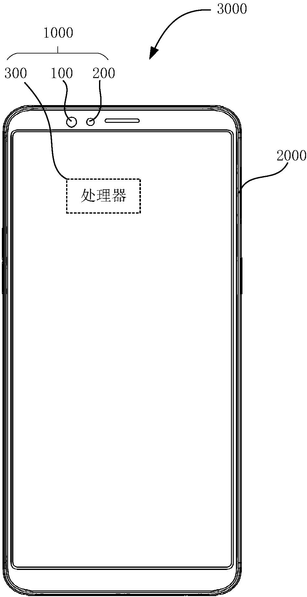
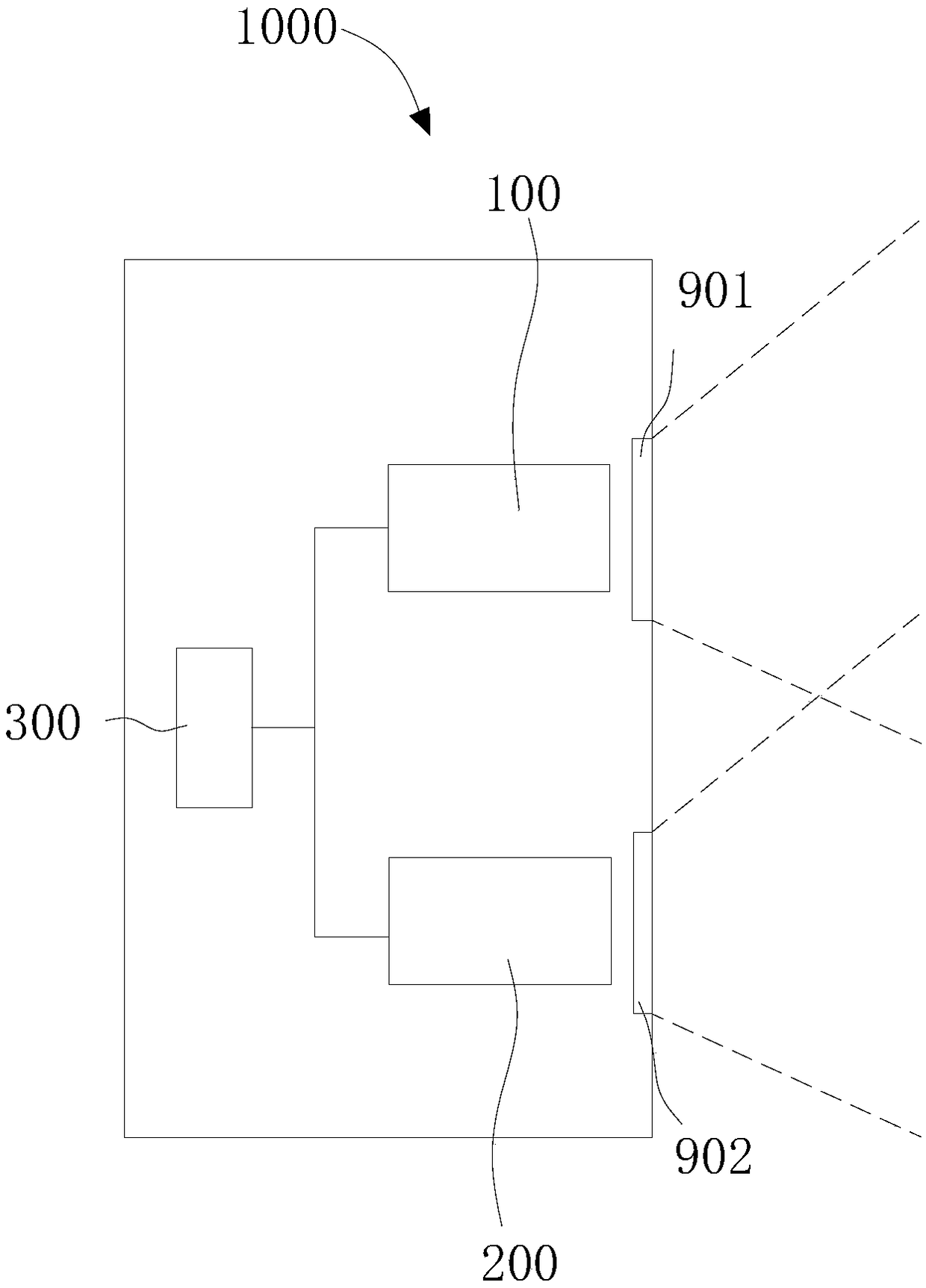
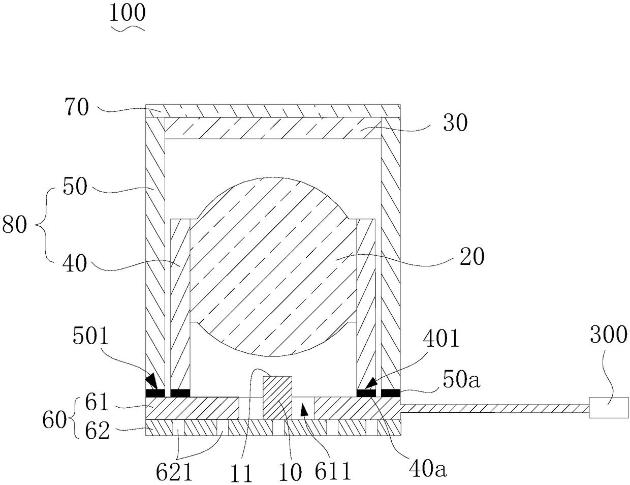
The invention discloses a laser projector, a camera module and an electronic device. The laser projector includes a substrate assembly, a barrel assembly, a light source, a collimating element, and adiffraction element. The barrel assembly is disposed on the substrate assembly. The lens barrel assembly includes a collimating bracket and a diffraction bracket, and the collimating bracket and the diffraction bracket are in a split structure. The light source is disposed on the substrate assembly for emitting laser light. The collimating element is supported by the collimating bracket for collimating the laser light emitted by the light source, the light source is an edge emitting laser, and the edge emitting laser includes a light emitting surface, and the light emitting surface faces the collimating element. The diffraction element is supported by the diffraction bracket for diffracting the laser light collimated by the collimating element to form a laser pattern. The laser projector,the camera module and the electronic device according to the embodiments of the present invention respectively support the collimating element and the diffraction element by using the split collimating bracket and the diffraction bracket, respectively, facilitating the installation and position adjustment of the collimating element and the diffraction element, and the mounting efficiency is high.

Description

technical field [0001] The invention relates to the technical field of three-dimensional imaging, in particular to a laser projector, a camera module and electronic equipment. Background technique [0002] Existing laser projectors usually have a small volume, so that the laser projector can be integrated into an electronic device, such as a mobile phone. When the volume of the laser projector is small, each component in the laser projector is also very small, so that it is easy to be damaged during installation or it is difficult to ensure high installation accuracy. Contents of the invention [0003] Embodiments of the present invention provide a laser projector, a camera module and electronic equipment. [0004] A laser projector according to an embodiment of the present invention includes a substrate assembly, a lens barrel assembly, a light source, a collimator element, and a diffraction element. The barrel assembly is disposed on the base assembly. The lens barrel...

Claims


Application Information

Patent Timeline
IPC IPC(8): G02B27/42G02B7/00G03B30/00
CPCG02B7/00G02B27/4205
Inventor 张学勇
Owner GUANGDONG OPPO MOBILE TELECOMM CORP LTD
Learn More