
Diffuse reflection LED line lamp

A technology of LED line lights and LED light strips, applied in reflectors, lighting devices, light sources, etc., can solve the problems of poor diffuse reflection LED line lights, inconvenient installation, different lengths of line lights, etc., to avoid specular reflection. , to meet the length requirements, improve the effect of light efficiency

Pending Publication Date: 2018-09-28
GUANGZHOU KERIDA OPTOELECTRONIC TECH CO LTD
View PDF11 Cites 0 Cited by
  • Summary
  • Abstract
  • Description
  • Claims
  • Application Information

AI Technical Summary

Problems solved by technology

However, due to the different use environments, the length of the required line lights is also different. In the use environment that requires a long length, the following two methods are usually used to meet this demand: one way is to use multiple LED lights The way of splicing strips, the LED light strip is set in the metal shell, that is, by removing the end cover of the diffuse reflection LED line light, and then splicing another LED light strip on the basis of one LED light strip, this kind of splicing is currently available. This method is inconvenient to install; another method is to directly replace a longer diffuse reflection LED line light, which still cannot meet some situations where the length requirement is extremely long
[0003] In addition, the light emitted by the LED light bar in the existing diffuse reflection LED line light will cause specular reflection on the metal shell, making the light effect of the diffuse reflection LED line light poor.

Method used


Image

  • Diffuse reflection LED line lamp
  • Diffuse reflection LED line lamp
  • Diffuse reflection LED line lamp

Examples


Embodiment Construction

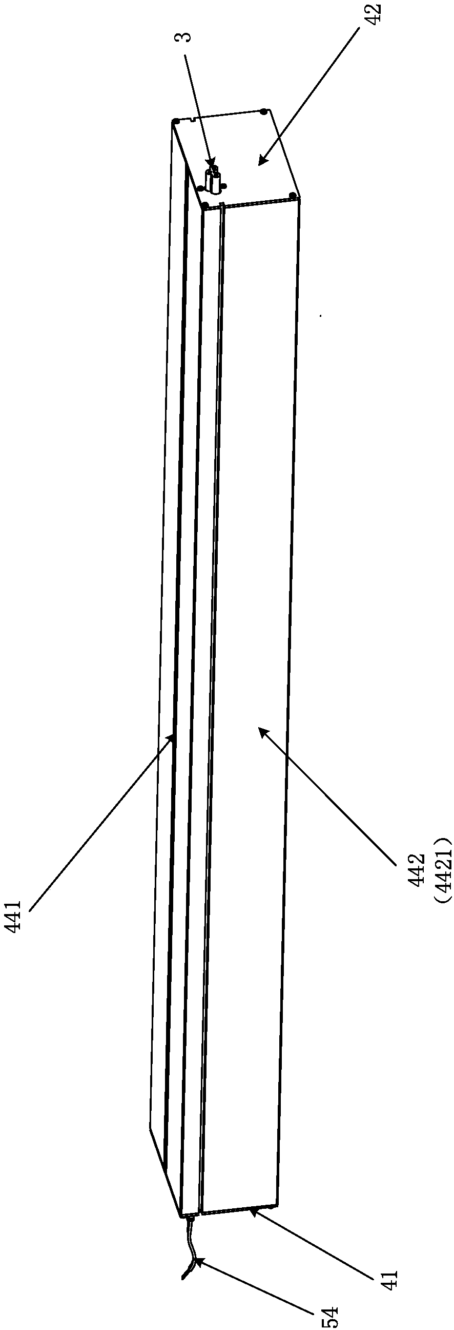
[0022] see Figure 1-6 , The diffuse reflection LED linear light of the present invention includes: a first linear light 1 , a second linear light 2 and a power connector 3 .

[0023] Both the first line light 1 and the second line light 2 include a first end cover 41, a second end cover 42, a bottom plate 43, a casing 44, a reflector 45, an LED light bar 46, a power supply 47, a power input line 48, a power supply The output wire 49 , the first input socket 50 and the second input socket 51 , wherein the shell 44 includes a top plate 441 and two side plates 442 oppositely disposed. That is, the first linear light 1 and the second linear light 2 have the same structural composition. The material of the shell 44 can be metal such as aluminum alloy, the bottom plate 43 can be a diffuser plate, and the first end cover 41 and the second end cover 42 can be specifically made of plastic.

[0024] The first end cover 41 and the second end cover 42 can be arranged relatively on both...


PUM


Abstract

The invention discloses a diffuse reflection LED line lamp. The diffuse reflection LED line lamp comprises a first line lamp body, a second line lamp body and a power connector. The first line lamp body and the second line lamp body each comprise a first end cover, a second end cover, a base plate, an outer shell, a reflecting piece, an LED lamp strip, a power source, a power source input line, apower source output line, a first input socket and a second input socket. One end of the power connector is connected with the other end of a second input socket of the first line lamp body, and the other end of the power connector is connected with the other end of a first input socket of the second line lamp body. In this way, the splicing mode of the diffuse reflection LED line lamp is convenient to implement; the length requirement for the diffuse reflection LED line lamp can be met; meanwhile, mirror surface reflection, onto a metal outer shell, of light rays can be avoided; and the lighting effect of the diffuse reflection LED line lamp is improved.

Description

technical field [0001] The invention relates to the technical field of lamps, in particular to a diffuse reflection LED line lamp. Background technique [0002] As the use of LED lights becomes wider and wider, diffuse reflection LED line lights are used in more and more occasions. However, due to the different use environments, the lengths of the required line lights are also different. In the use environments that require a long length, the following two methods are usually used to meet this demand: one way is to use multiple LED lights The way of splicing strips, the LED light strip is set in the metal shell, that is, by removing the end cover of the diffuse reflection LED line light, and then splicing another LED light strip on the basis of one LED light strip, this kind of splicing is currently available. This method is inconvenient to install; another method is to directly replace a diffuse reflection LED line light with a longer length, which still cannot meet some s...

Claims


Application Information

Patent Timeline
Patent Type & Authority Applications(China)
IPC IPC(8): F21S4/28F21V21/002F21V21/005F21V7/00F21Y115/10
CPCF21S4/28F21V7/00F21V21/002F21V21/005F21Y2115/10
Inventor 李旭辉赖云辉
Owner GUANGZHOU KERIDA OPTOELECTRONIC TECH CO LTD
Learn More