
Rack assembly for stabilizer and stabilizer

A stabilizer and frame technology, applied in the direction of machines/supports, instruments, cameras, etc., can solve the problems of reducing the cameraman's arm strength requirements and saving labor, and the battery compartment volume is reduced, which cannot be realized, so that it is not easy to be confused, easy to operate, The effect of improving space utilization

Active Publication Date: 2018-09-28
GUILIN ZHISHEN INFORMATION TECH CO LTD
View PDF11 Cites 18 Cited by
  • Summary
  • Abstract
  • Description
  • Claims
  • Application Information

AI Technical Summary

Problems solved by technology

This rack with a slender rod-like structure has the following problems: when the handheld gimbal carries the camera, at least 60% of the total weight of the gimbal and the camera will be concentrated at the camera position, that is, the camera and The overall center of gravity of the gimbal will be a certain distance higher than the part where the user holds the handheld gimbal
But in fact, since the two handles on the crossbar make the distance between the hands and the stabilizer and the camera farther, the photographer is required to open his arms to hold it, which does not reduce the cameraman's arm strength requirements and save effort desire
[0004] At the same time, since the overall center of gravity of the hand-held gimbal with a camera is mainly concentrated on the upper part close to the camera, the overall center of gravity is far away from the grip part held by the user, and it is easy to cause the gimbal to shake
If the distance between the overall center of gravity of the handheld gimbal and the camera and the user's grip is to be reduced, the area of ​​the functional area used to operate the buttons and the volume of the battery compartment for accommodating the battery will be reduced, which will improve the functionality of the handheld gimbal and operation time increase is greatly disadvantageous

Method used


Image

  • Rack assembly for stabilizer and stabilizer
  • Rack assembly for stabilizer and stabilizer
  • Rack assembly for stabilizer and stabilizer

Examples


Embodiment Construction

[0049] A schematic solution of the rack assembly disclosed in the present invention will now be described in detail with reference to the accompanying drawings. Although the drawings are provided to illustrate certain embodiments of the invention, the drawings are not necessarily to scale of particular embodiments and certain features may be exaggerated, removed, or partially sectioned to better illustrate and explain aspects of the invention. public content. Some components in the drawings can be adjusted according to actual needs without affecting the technical effect. Appearances of the phrase "in the drawings" or similar terms in the specification do not necessarily refer to all drawings or examples.

[0050] It should be noted that when an element is referred to as being "fixed" to another element, it can be directly on the other element or an intervening element can also exist. When a component is said to be "connected" to another component, it may be directly connecte...


PUM


Abstract

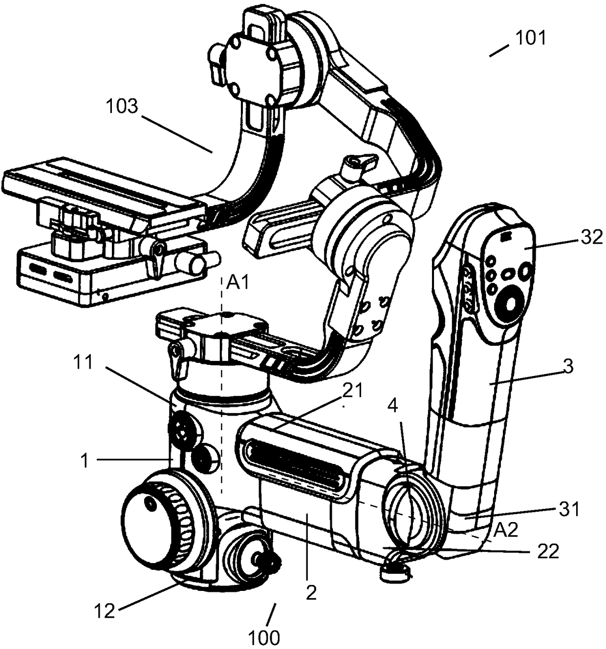
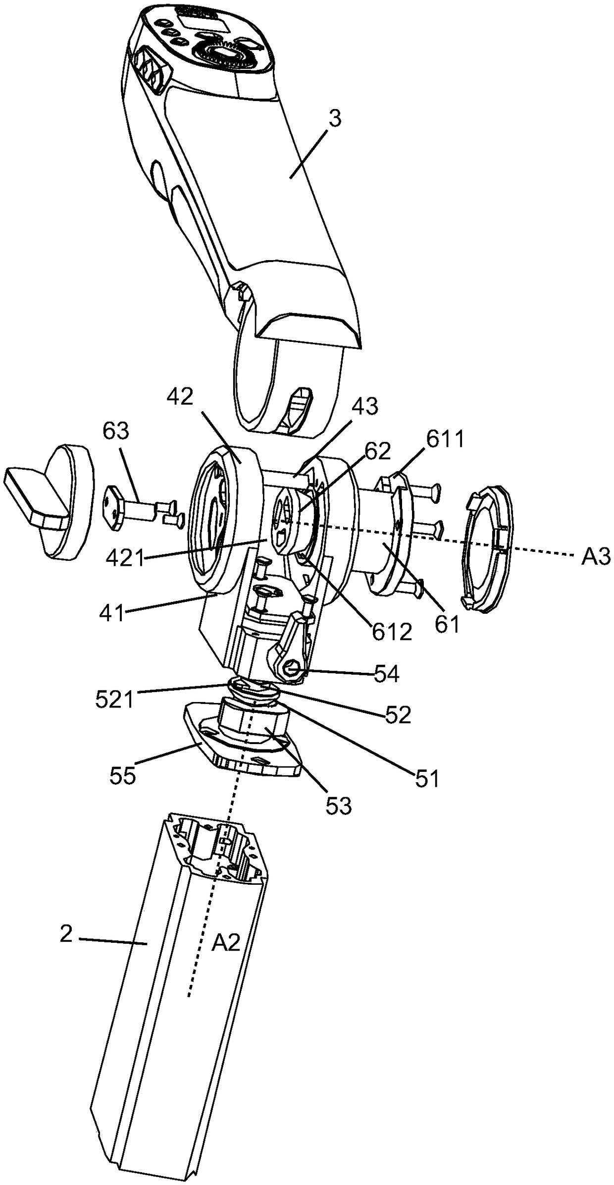
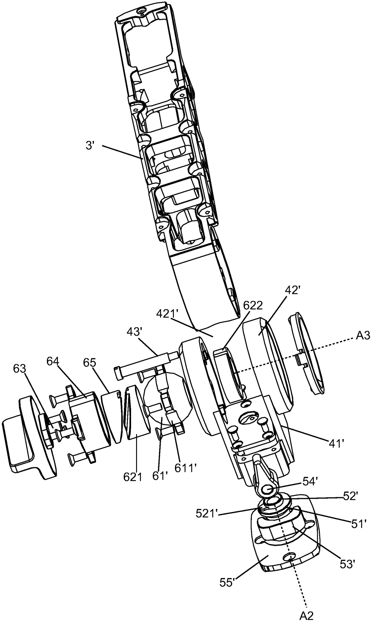
The invention provides a rack assembly for a stabilizer. The stabilizer comprises a cradle head for fixing a shooting device and adjusting the attitude of the shooting device. The rack assembly is used for bearing the cradle head, and comprises a first rack part, a second rack part and a holding rod. It is configured that an angle is formed between the second rack part and the first rack part. Therack assembly is configured to allow the holding rod to hold the stabilizer in the manner that the holding rod approximately vertically aligns at the overall gravity center of the stabilizer and theshooting device. Thus, the stabilizer which conforms to ergonomics and has good stability and variable operation attitudes and the rack assembly thereof are provided. Furthermore, the invention provides the stabilizer with the rack assembly.

Description

technical field [0001] The invention relates to the technical field of stabilizers, in particular to a frame assembly for holding a stabilizer installed with a shooting device in a labor-saving manner and having a high space utilization rate. Further, the present invention also relates to a stabilizer with the frame assembly. Background technique [0002] It is known that the existing hand-held stabilizers are generally composed of a pan-tilt that can fix the shooting device and a frame that is connected to the pan-tilt at one end and is used to support the pan-tilt, wherein the frame is generally an upright rod The structure can be held by the photographer and used to lift the shooting part when shooting. Because the operation keys of the handheld stabilizer and the batteries required for the work of the handheld stabilizer are all arranged in the frame, this often makes the frame very long. This rack with a slender rod-like structure has the following problems: when the ...

Claims


Application Information

Patent Timeline
Patent Type & Authority Applications(China)
IPC IPC(8): F16M13/04F16M11/12F16M11/18
CPCF16M11/121F16M11/18F16M13/04F16M2200/042F16M2200/041F16M13/00F16M11/205F16M11/048F16M11/2021F16M11/123G03B17/561
Inventor 廖易仑
Owner GUILIN ZHISHEN INFORMATION TECH CO LTD
Learn More