A degassing device

A defoaming, curved body technology, applied in the directions of liquid degassing, separation methods, chemical instruments and methods, etc., can solve the problems of low efficiency, poor defoaming effect of the defoaming device, etc., to lengthen the flow path and improve the defoaming effect. Efficiency, the effect of increasing the exposed area

Active Publication Date: 2020-05-01
YUNGU GUAN TECH CO LTD
View PDF3 Cites 0 Cited by
  • Summary
  • Abstract
  • Description
  • Claims
  • Application Information

AI Technical Summary

Problems solved by technology

[0005] Therefore, the technical problem to be solved by the present invention is that the degassing effect of the degassing device in the prior art is poor and the problem of low efficiency

Method used


Image

  • A degassing device
  • A degassing device
  • A degassing device

Examples


Embodiment 1

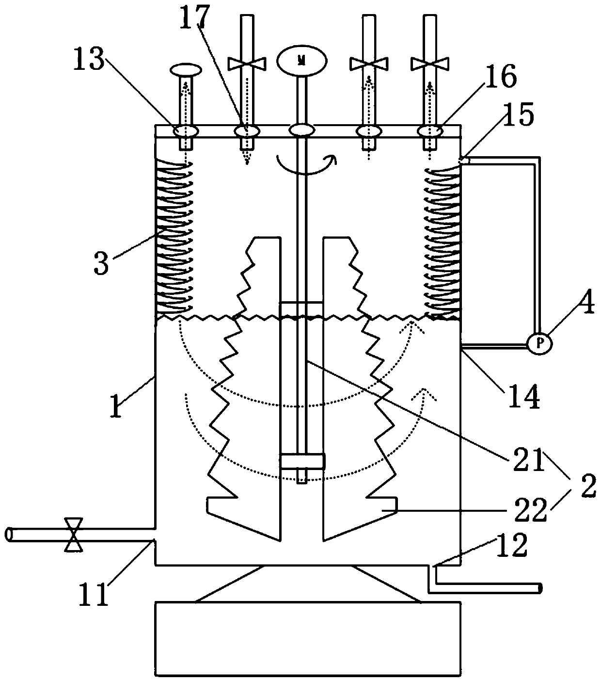
[0044] This embodiment provides a degassing device, such as figure 1 As shown, it includes a cylinder body 1 , a stirring assembly 2 and a multi-layer spread structure 3 ; among two vertically adjacent spread structures 3 , the upper spread structure 3 is sleeved on the lower spread structure 3 .

[0045] Wherein, the barrel 1 has an inner cavity, a liquid inlet 11 and a liquid outlet 12 communicating with the inner cavity are opened on the side wall, and an exhaust port 13 is opened on the top wall.

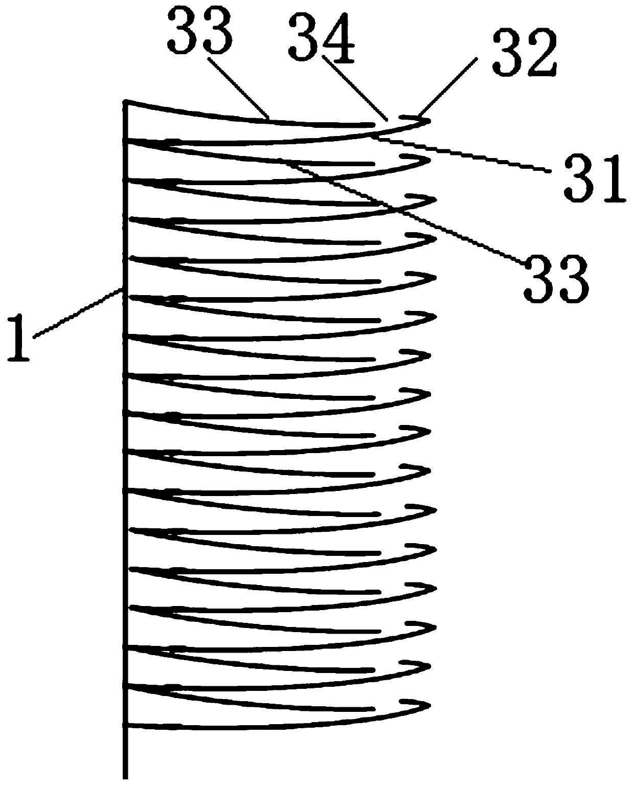
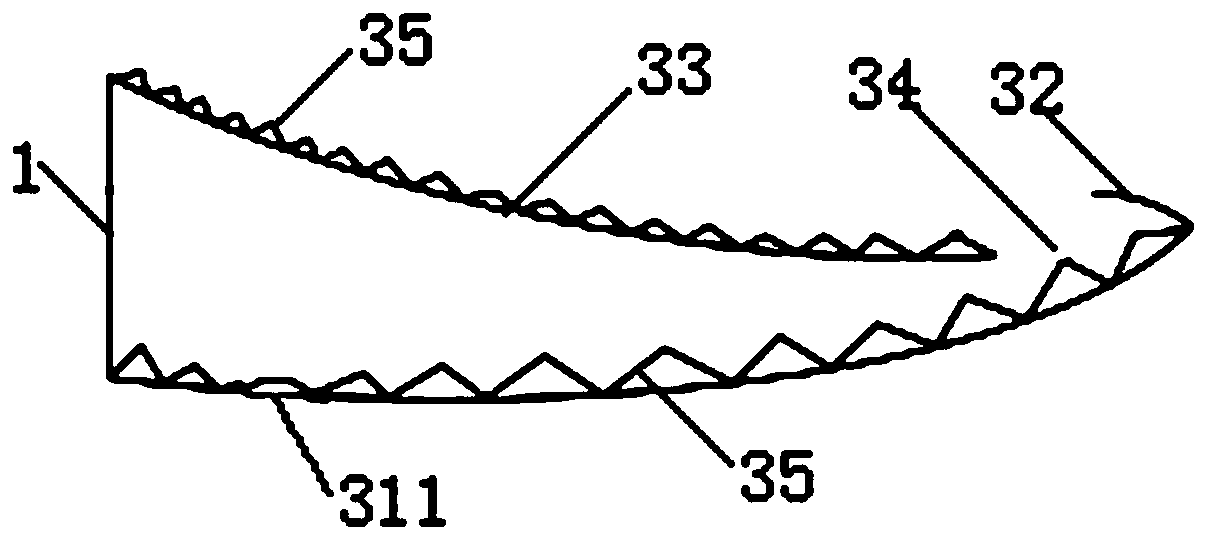
[0046] like figure 2 As shown, any layer of the spread structure 3 includes a meandering curved surface body 32 , a main curved surface body 31 and a diversion curved surface body 33 arranged in sequence from top to bottom, and the spread structure 3 has a ring structure as a whole. An inner hole is provided in the middle of the spreading structure 3 , and the spreading structure 3 is sheathed outside the stirring assembly 2 through the inner hole, and a required distance is r...

Embodiment 2

[0065] This embodiment provides a degassing device. Compared with the degassing device provided in Example 1, the difference is that the degassing device is not provided with a vacuum device, and correspondingly, the first wall is not provided on the top wall of the cylinder body 1. Three openings 16, the gas formed during the degassing process of the solution is naturally discharged through the exhaust port 13.

Embodiment 3

[0067] This embodiment provides a degassing device, which is different from the degassing device provided in Embodiment 1 or Embodiment 2 in that the nitrogen delivery equipment can also be replaced by other inert gas delivery equipment, such as neon gas .

[0068] As an alternative embodiment, the gas conveying device can also be replaced by a water pump, and the solution is drawn out from the liquid outlet 12 through the liquid outlet 12 .

[0069] As a further alternative embodiment, the degassing device may not be provided with the gas delivery device. After the solution is defoamed, the solution is discharged from the liquid outlet 12 under its own gravity. In this embodiment, the liquid outlet 12 is opened on the bottom wall of the cylinder.


PUM


Abstract

The invention discloses a defoaming device. The defoaming device comprises a cylinder body, a stirring assembly and at least one spreading structure layer. The spreading structure sleeves the stirringassembly in the cylinder body. A desired gap is formed between the inner hole and the outer wall of the stirring assembly. The spreading structure is fixed to the inner wall of the cylinder body. Anylayer of the spreading structure comprises a main curved body for solution spreading. In solution defoaming, a solution is conveyed into the cylinder body through a liquid inlet, the stirring assembly continuously stirs the solution and introduces the solution to the main curved body, the solution is spread on the surface of the main curved body so that the exposed area of the solution is increased and foam is discharged, the spread solution falls to the next layer of the spreading structure through flow through holes of the main curved body drop by drop and then is spread again, and by analogy, the solution is continuously spread and the exposed area of the solution is further increased so that the defoaming effect and defoaming efficiency of the defoaming device are improved.

Description

technical field [0001] The invention relates to the technical field of gas-liquid separation, in particular to a degassing device. Background technique [0002] Before coating the liquid with high viscosity, the air bubbles in the liquid need to be discharged to reduce the content of air bubbles in the liquid. In the prior art, a degassing device is commonly used to degas the liquid, and the degassing device mainly includes a hollow cylinder, a stirring component and a vacuuming component. Among them, the side wall of the hollow cylinder is provided with a feed port and a discharge port, and the top surface is provided with an exhaust port; the vacuum assembly is connected to the exhaust port; the stirring assembly includes a stirring shaft vertically installed in the cylinder, And the impeller fixed on the stirring shaft. [0003] When the defoaming device of this structure performs defoaming treatment on the solution, the solution is transported into the cylinder through...

Claims


Application Information

Patent Timeline
Patent Type & Authority Patents(China)
IPC IPC(8): B01D19/00
CPCB01D19/0026
Inventor 曾宪祥
Owner YUNGU GUAN TECH CO LTD
Why Eureka
Try Eureka