
Soil replacement flowerpot capable of removing connection between soil and flowerpot

A technology of flower pots and soil, applied in botany equipment and methods, horticulture, container cultivation, etc., can solve the problems of flowers and plants being torn, and achieve the effect of protecting roots and avoiding being torn

Active Publication Date: 2018-09-28
金丽秋
View PDF13 Cites 3 Cited by
  • Summary
  • Abstract
  • Description
  • Claims
  • Application Information

AI Technical Summary

Problems solved by technology

[0008] Aiming at the deficiencies of the prior art, the present invention provides a soil-replacing flowerpot capable of removing the connection between the soil and the flowerpot, which solves the problem that when the flowerpot is directly removed, the connection between the soil and the flowerpot is tight, and the soil follows the flowerpot Connect together to remove the problem that the roots of flowers and plants are torn off

Method used


Image

  • Soil replacement flowerpot capable of removing connection between soil and flowerpot
  • Soil replacement flowerpot capable of removing connection between soil and flowerpot
  • Soil replacement flowerpot capable of removing connection between soil and flowerpot

Examples


Embodiment 1

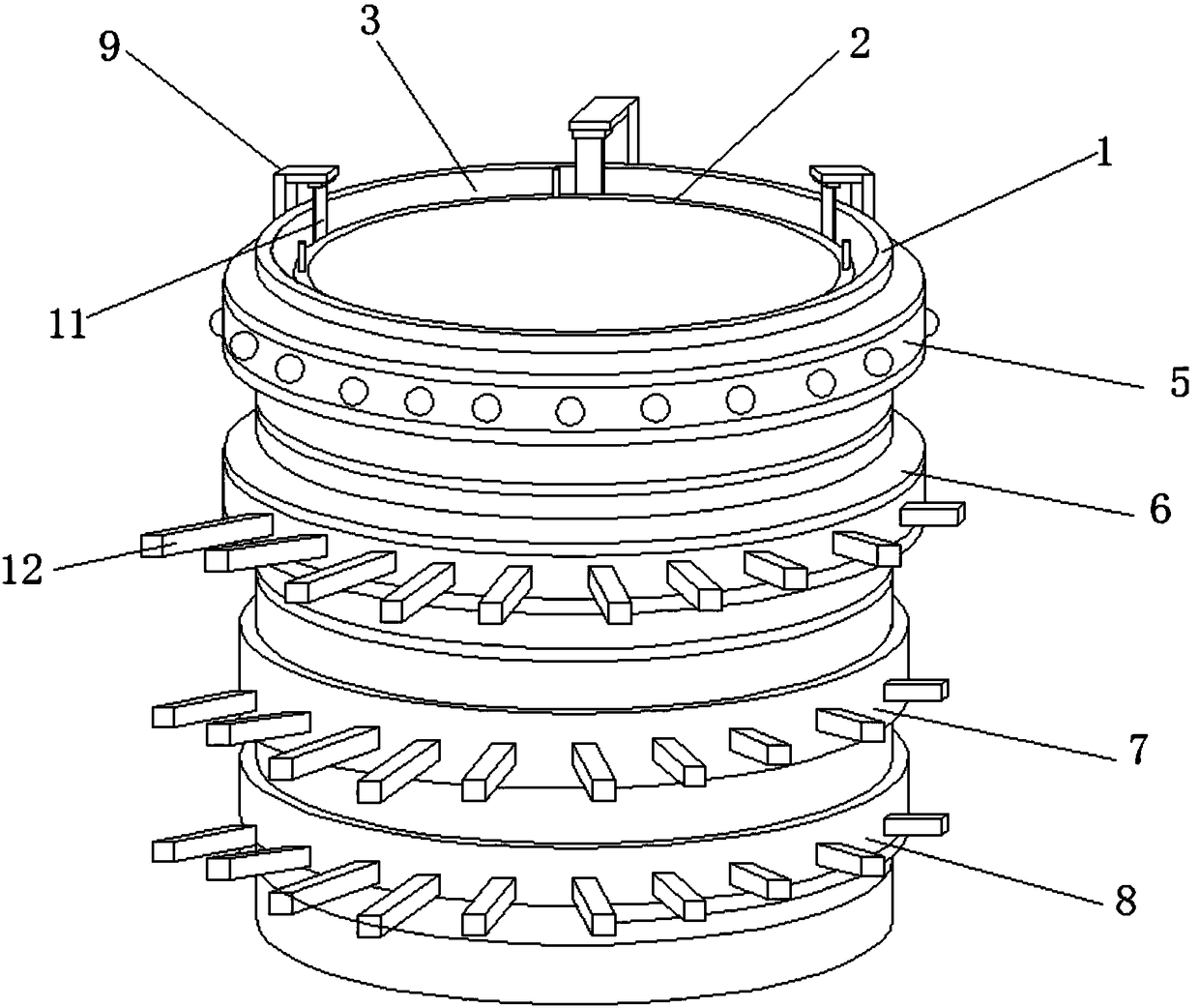
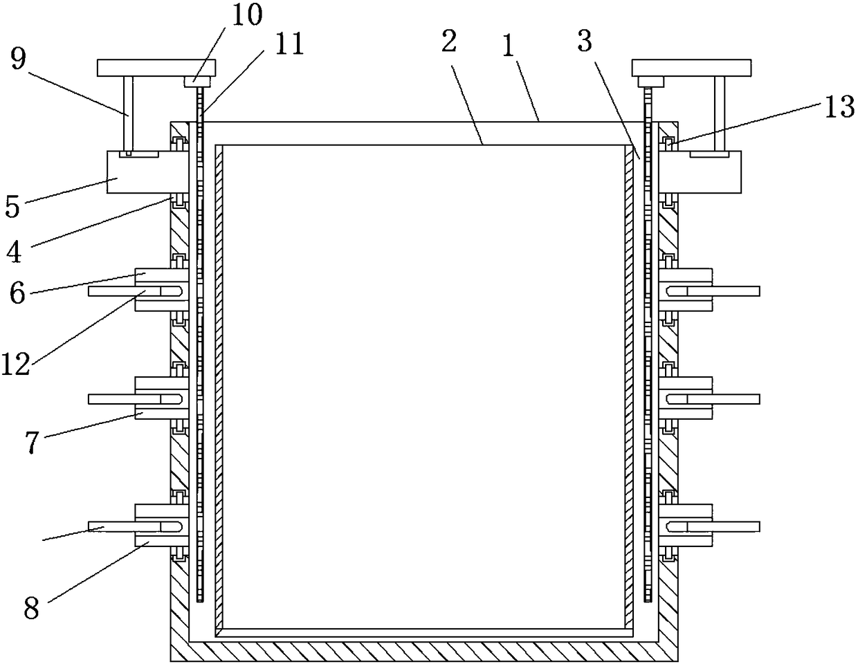
[0051] see Figure 1-2 , a soil-replacing flowerpot equipped with a connection between the removed soil and the flowerpot, comprising an outer pot 1 and an inner pot 2, the inner pot 2 is placed in the placement area of ​​the outer pot 1, and the inner pot 2 and the outer pot 1 There is an elastic area 3 between them, and four parallel ring grooves 4 are sequentially opened on the outer wall of the outer basin 1 from top to bottom, and a first sliding ring 5 and a second sliding ring 6 are set on the outer basin 1. , The third slip ring 7 and the fourth slip ring 8.

[0052] And the first sliding ring 5 , the second sliding ring 6 , the third sliding ring 7 and the fourth sliding ring 8 are sequentially slidably connected in the four ring grooves 4 from top to bottom.

[0053] The second slide ring 6, the third slide ring 7 and the fourth slide ring 8 are all provided with a redirection device 12, the redirection device 12 includes a telescopic piece 121, and the movable end ...

Embodiment 2

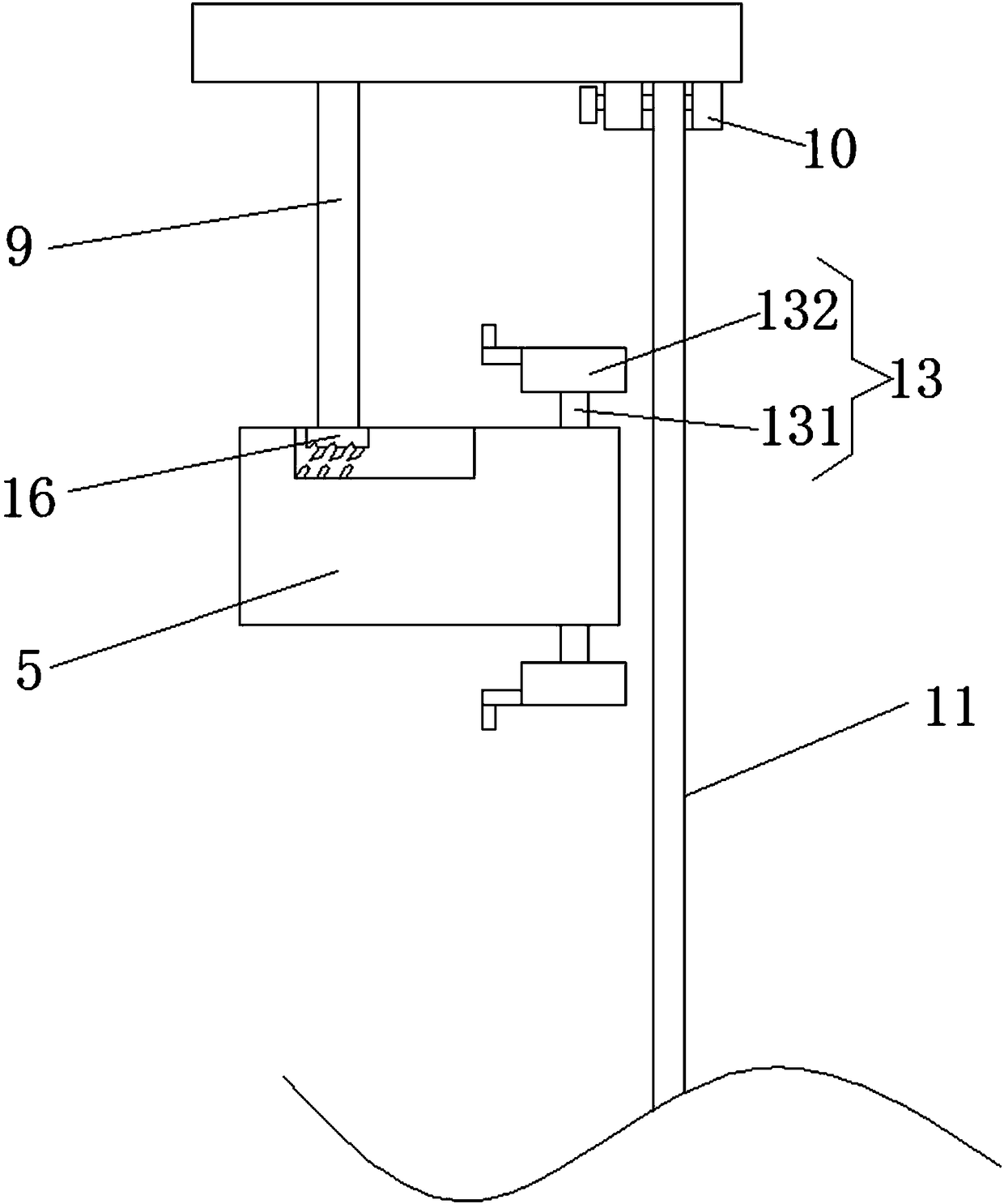
[0059] see image 3 , the top and bottom of the first slide ring 5, the second slide ring 6, the third slide ring 7 and the fourth slide ring 8 are all provided with limit guide blocks 13, which are used to limit and connect, and connect the slide rings in the ring grooves 4, on the inner wall of the ring groove 4, there is a limit guide groove 14 that is compatible with the limit guide block 13. The limit guide groove 14 also has the function of limiting and connecting. The limit guide block 13 includes a connecting column 131 , one end of the connecting column 131 extends into the limiting guide groove 14 and connects with the sliding group 132 disposed therein, and the rest of the features are the same as in the first embodiment.

Embodiment 3

[0061] see Figure 1-2 , on the basis of the embodiment 1-2, the limit guide block 13 and the limit guide groove 14 are added. When in use, the four sliding rings are prevented from being separated from the outer basin 1, so that the four sliding rings can be stably placed in the outer basin 1 to slide and turn.

[0062] The first slip ring 5, the second slip ring 6, the third slip ring 7 and the fourth slip ring 8 not only have the effect of rotation, but also the effect achieved by the rotation of each slip ring is different. The rotation of the first slip ring 5 is to drive Remove the soil piece 11 and rotate to break the soil for the first time, and there is also a sliding block 16 on the first sliding ring 5. By adjusting the distance that the soil removal piece 11 advances, the soil breaking distance of the soil removal piece 11 is adjusted. When in use, According to the softness of the soil, use the corresponding ruler to measure the distance of breaking the soil, expa...


PUM


Abstract

The invention provides a soil replacement flowerpot capable of removing connection between soil and a flowerpot. The soil replacement flowerpot comprises an outer pot body and an inner pot body, wherein the inner pot body is arranged in an accommodating area of the outer pot body, an elastic area is reserved between the inner pot body and the outer pot body, four parallel annular grooves are sequentially formed in an outer wall of the outer pot body from top to bottom, a first sliding ring, a second sliding ring, a third sliding ring and a fourth sliding ring sleeves the outer pot body, and the first sliding ring, the second sliding ring, the third sliding ring and the fourth sliding ring are sequentially in sliding connection into the four annular grooves from top to bottom; an N-shaped extending rod is arranged on the first sliding ring, the downwards extending end of the extending rod is connected with a soil removing sheet, the soil removing sheet is arranged in the elastic area, and the movable end of the soil removing sheet extends to the bottom of the elastic area. The soil replacement flowerpot capable of removing connection between the soil and the flowerpot disclosed by the invention solves the problem that when the flowerpot is directly removed, the soil and the flowerpot are removed together, and root hair of flowers and plants are pulled apart.

Description

technical field [0001] The invention relates to the technical field of flower pots, in particular to a soil-replacing flower pot equipped with connections between soil removal and flower pots. Background technique [0002] Potted flowers and plants need to be replaced frequently. The purpose of changing soil for flower pots is to provide stable nutrition for flowers and plants, so that they can grow stably. For the convenience of soil replacement, many types of flower pots are derived. For example, the Chinese patent disclosure A new type of water storage and soil replacement flowerpot (application number: CN201620161632.0), the patent includes the upper pot body, the middle pot body, the bottom pot body, the lower part of the upper pot body is connected with the upper part of the middle pot body through the screw port …The bottom pot is made of high-density sponge, and the middle of the bottom pot is protruding. There are ventilation holes around the protruding part and the...

Claims


Application Information

Patent Timeline
IPC IPC(8): A01G9/02
Inventor 吕文辉
Owner 金丽秋
Learn More