
Transmission mechanism of mini-tiller

The technology of a transmission mechanism and a micro-tiller, which is applied in the field of micro-tillers, can solve the problems that the rotary tiller cannot be cultivated, the transmission mechanism is unsuitable, and the transmission mechanism is large in size, etc., and achieves the effects of reducing the height, reducing the thrust, and reducing the work intensity.

Pending Publication Date: 2018-09-25
CHONGQING ZHUOGE HAOSI MACHINERY
View PDF0 Cites 0 Cited by
  • Summary
  • Abstract
  • Description
  • Claims
  • Application Information

AI Technical Summary

Problems solved by technology

However, the transmission mechanism of the micro-tillage machine has a large volume, which makes the height of the whole micro-tillage machine higher, so that the rotary tiller can not plow the land on the edge of the greenhouse, so the transmission mechanism of the existing micro-tillage machine is not suitable for use in greenhouses. use

Method used


Image

  • Transmission mechanism of mini-tiller
  • Transmission mechanism of mini-tiller
  • Transmission mechanism of mini-tiller

Examples


Embodiment Construction

[0017] The following is further described in detail through specific implementation methods:

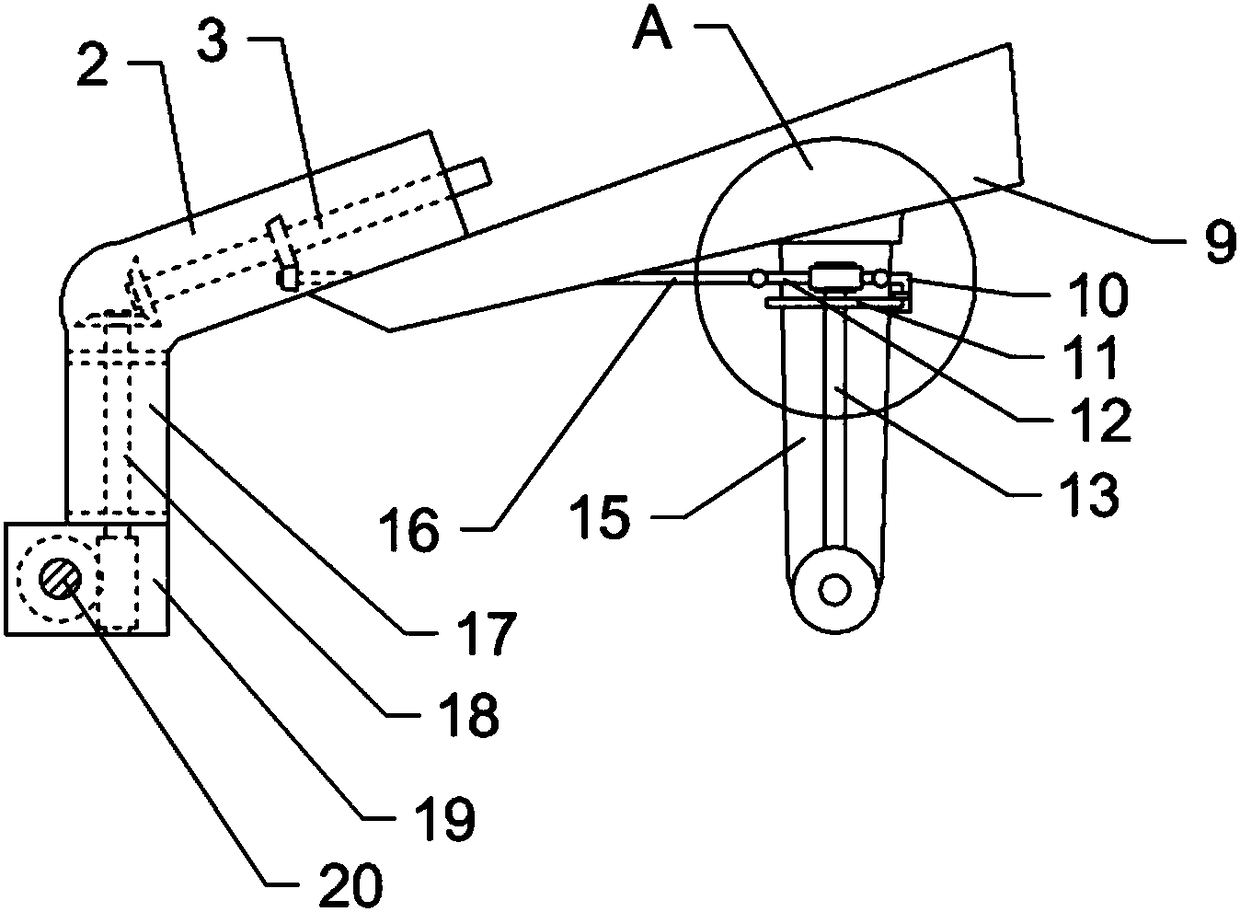
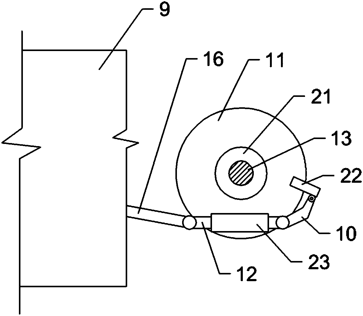
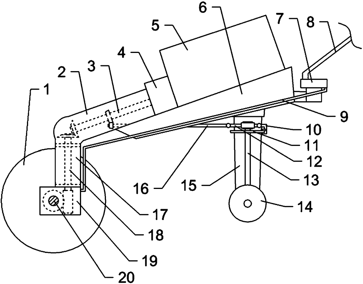
[0018] The reference signs in the drawings of the description include: rotary tiller mechanism 1, box body 2, first transmission shaft 3, clutch 4, power mechanism 5, frame 6, turntable 7, armrest 8, connecting rod 9, adjustment bracket 10, Fixed plate 11, adjustment shaft 12, first rotating shaft 13, roller 14, support frame 15, third transmission shaft 16, protective box 17, second transmission shaft 18, rotary tillage box 19, rotary tillage shaft 20, adjustment worm wheel 21, Clamping piece 22, adjusting worm 23.

[0019] The embodiment is basically as attached figure 1 with figure 2 As shown: the transmission mechanism of the tiller includes a frame 6, on which a box body 2 is fixedly connected along the length direction, and the inside of the box body 2 is connected with a first transmission shaft 3 along the length direction for rotation, and the first transmission shaft 3 ...


PUM


Abstract

The invention relates to the technical field of mini-tillers, in particular to a transmission mechanism of a mini-tiller. The transmission mechanism comprises a machine frame, a box body is fixedly connected to the machine frame in the length direction, a first transmission shaft is connected to the interior of the box body in a rotating mode, a protection box is fixedly connected to one end of the box body, a rotary tillage box is connected to the lower end of the protection box in a rotating mode, a rotary tillage shaft is connected to the rotary tillage box in a rotating mode, a second transmission shaft is arranged between the rotary tillage shaft and the first transmission shaft, a supporting frame is connected to the lower side of the machine frame in a rotating mode, a vertical first rotating shaft is connected to the supporting frame in a rotating mode, a third transmission shaft is arranged between the first rotating shaft and the first transmission shaft, an adjusting shaft is connected to the end, close to the first rotating shaft, of the third transmission shaft, an adjusting worm is arranged on the adjusting shaft, an adjusting worm wheel matched with the adjusting worm in a clutch mode is arranged on the first rotating shaft, and a supporting mechanism used for supporting the adjusting shaft for deflection is arranged at the end, far away from the third transmission shaft, of the adjusting shaft. According to the scheme of the transmission mechanism, the problem that in the prior art, a transmission mechanism of a mini-tiller is inapplicable in a greenhouse can be solved.

Description

technical field [0001] The invention relates to the technical field of micro tillage machines, in particular to a transmission mechanism of micro tillage machines. Background technique [0002] Tillers are powered by small diesel engines or gasoline engines, and have the characteristics of light weight, small size, and simple structure. Tillers are widely used in dry land, paddy fields, orchards, etc. in plains, mountains, and hills. Equipped with corresponding equipment, it can be used for pumping, power generation, spraying, spraying and other operations, and can also be towed for short-distance transportation. The tiller can be used freely in the field, which is convenient for users to use and store, eliminating the need for large-scale agricultural machinery to enter The troubles of mountainous fields are the best choice for farmers and consumers to replace cattle plowing. [0003] The structure of the micro tillage machine mainly has a frame with handrails on the fram...

Claims


Application Information

Patent Timeline
Patent Type & Authority Applications(China)
IPC IPC(8): A01B33/08
CPCA01B33/082
Inventor 刘国印
Owner CHONGQING ZHUOGE HAOSI MACHINERY
Learn More