Optical device module and mobile terminal

A technology of optical devices and mobile terminals, which is applied in the direction of electrical components, electromagnetic transmitters, telephone structures, etc., can solve problems such as the inability to achieve screen coverage, and achieve the effects of improving screen coverage, increasing screen coverage, and reducing complexity

Active Publication Date: 2018-09-18
BEIJING XIAOMI MOBILE SOFTWARE CO LTD
View PDF9 Cites 26 Cited by
  • Summary
  • Abstract
  • Description
  • Claims
  • Application Information

AI Technical Summary

Problems solved by technology

[0003] In order to overcome the problem in the related art that there is a large area on the forehead or chin of a mobile terminal that cannot achieve screen coverage, the present disclosure provides an optical device module and a mobile terminal

Method used


Image

  • Optical device module and mobile terminal
  • Optical device module and mobile terminal
  • Optical device module and mobile terminal

Examples


Embodiment Construction

[0049] Reference will now be made in detail to the exemplary embodiments, examples of which are illustrated in the accompanying drawings. When the following description refers to the accompanying drawings, the same numerals in different drawings refer to the same or similar elements unless otherwise indicated. The implementations described in the following exemplary examples do not represent all implementations consistent with the present disclosure. Rather, they are merely examples of apparatuses and methods consistent with aspects of the present disclosure as recited in the appended claims.

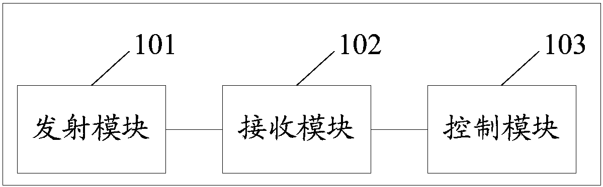
[0050] figure 1 is a block diagram of an optical device module shown according to an exemplary embodiment, see figure 1 , the optical device module includes: a transmitting module 101 , a receiving module 102 and a control module 103 . Wherein, the transmitting module 101 includes a transmitter array, and the transmitter array is used to transmit laser signals; the receiving module 1...


PUM


Abstract

The invention relates to an optical device module and a mobile terminal, and belongs to the technical field of mobile terminals. The optical device module comprises a transmission module including a transmitter array, wherein the transmitter array is used for transmitting laser signals; a receiving module including a receiver array, wherein the receiver array is used for receiving reflected lightsignals and generating electric signals, wherein the reflected light signals are generated after the laser signals are reflected by an object; and a control module used for receiving a command signalsent by the mobile terminal, and controlling the transmitter array and a transmitter and the work of a receiver corresponding to the command signal in the transmitter array according to a module function indicated by the command signal, wherein the module function includes ranging, image photographing, face recognition, and photography lamps.

Description

technical field [0001] The present disclosure relates to the field of mobile terminals, in particular to an optical device module and a mobile terminal. Background technique [0002] With the development of mobile terminal technology, mobile terminals such as mobile phones have entered the era of full screens. However, the current full screen is not a full screen in the true sense. The front of the mobile terminal usually needs to be equipped with a front camera, a proximity sensor (Proximity Sensor), a flood light (Flood Light), etc., resulting in a large gap between the forehead or the chin of the mobile terminal. Screen coverage cannot be achieved for large areas. Contents of the invention [0003] In order to overcome the problem in the related art that there is a large area on the forehead or chin of a mobile terminal that cannot be covered by a screen, the present disclosure provides an optical device module and a mobile terminal. [0004] According to a first aspe...

Claims


Application Information

Patent Timeline
Patent Type & Authority Applications(China)
IPC IPC(8): H04M1/02H04M1/725H04B10/50
CPCH04B10/503H04M1/026H04M1/0264H04M1/72448
Inventor 陈朝喜
Owner BEIJING XIAOMI MOBILE SOFTWARE CO LTD
Why Eureka
Try Eureka