
Lock convenient to open

An opening and lock technology, applied in the field of locks, can solve the problems of inconvenience and cumbersome unlocking operations, and achieve the effects of easy operation, simple overall structure, and easy sliding and swing limit control.

Active Publication Date: 2018-09-14
中山市欧柏克五金制品有限公司
View PDF9 Cites 0 Cited by
  • Summary
  • Abstract
  • Description
  • Claims
  • Application Information

AI Technical Summary

Problems solved by technology

[0002] The deadbolt of traditional locks can only expand and contract horizontally along the lock body (that is, the deadbolt can only slide horizontally on the housing, and cannot swing back and forth). It is necessary to reversely twist the handle until the deadbolt is completely retracted into the lock body, and then push the door body inward to realize the door opening operation. However, the unlocking operation of this kind of door body still has the following disadvantages: (1) because the deadbolt It cannot swing back and forth. When unlocking the door, the user needs to turn the direction of the handle accurately, and turn the handle in the opposite direction to the end position, so that the bolt completely exits the bolt hole of the door frame (that is, the bolt is completely retracted into the lock body). And by pushing the door body, the unlocking operation of the door body can be realized. However, in actual operation, the door body is still locked because the handle is not completely turned to the end position, and the dead bolt does not fully withdraw from the dead bolt hole of the door frame. Therefore, the unlocking operation is cumbersome and inconvenient

Method used


Image

  • Lock convenient to open
  • Lock convenient to open
  • Lock convenient to open

Examples


Embodiment

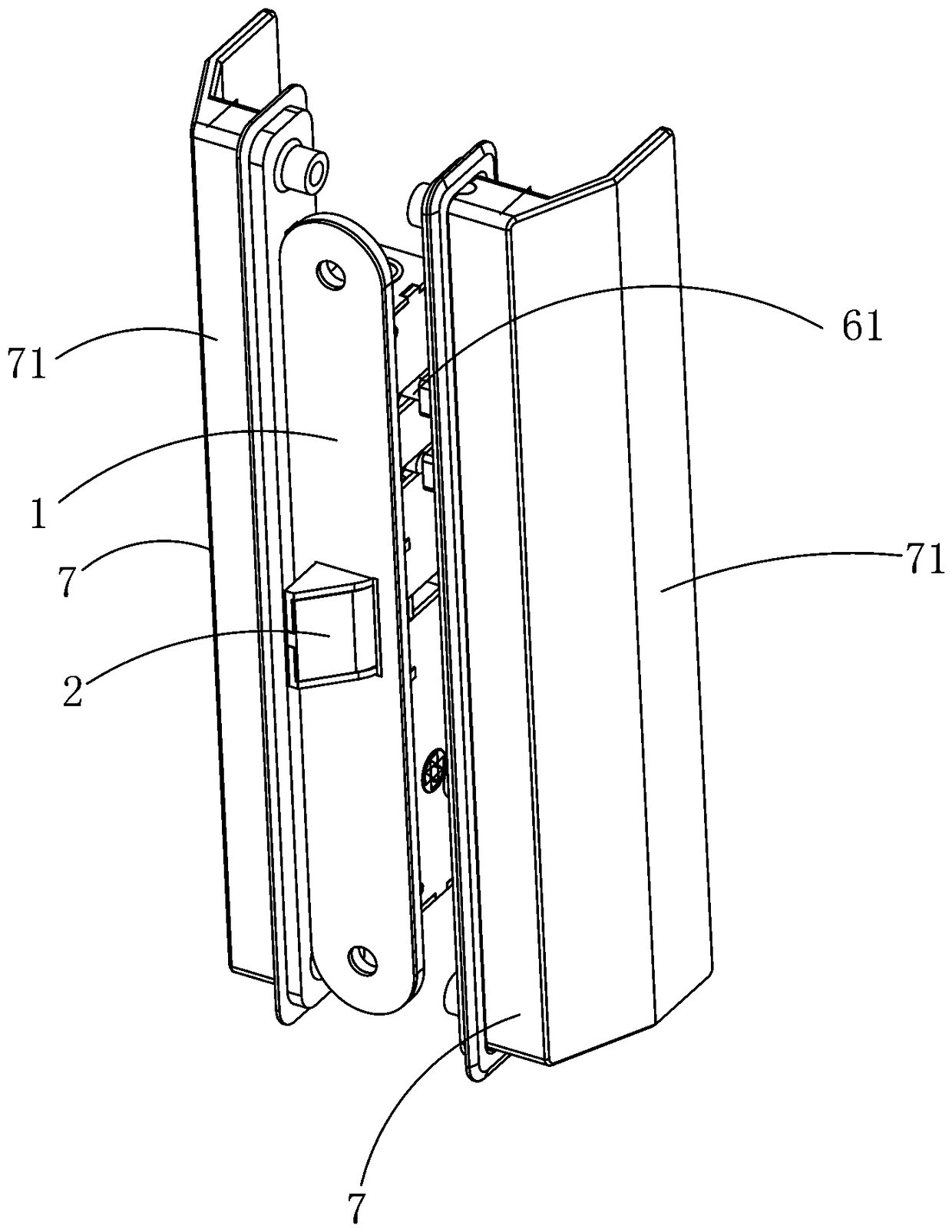
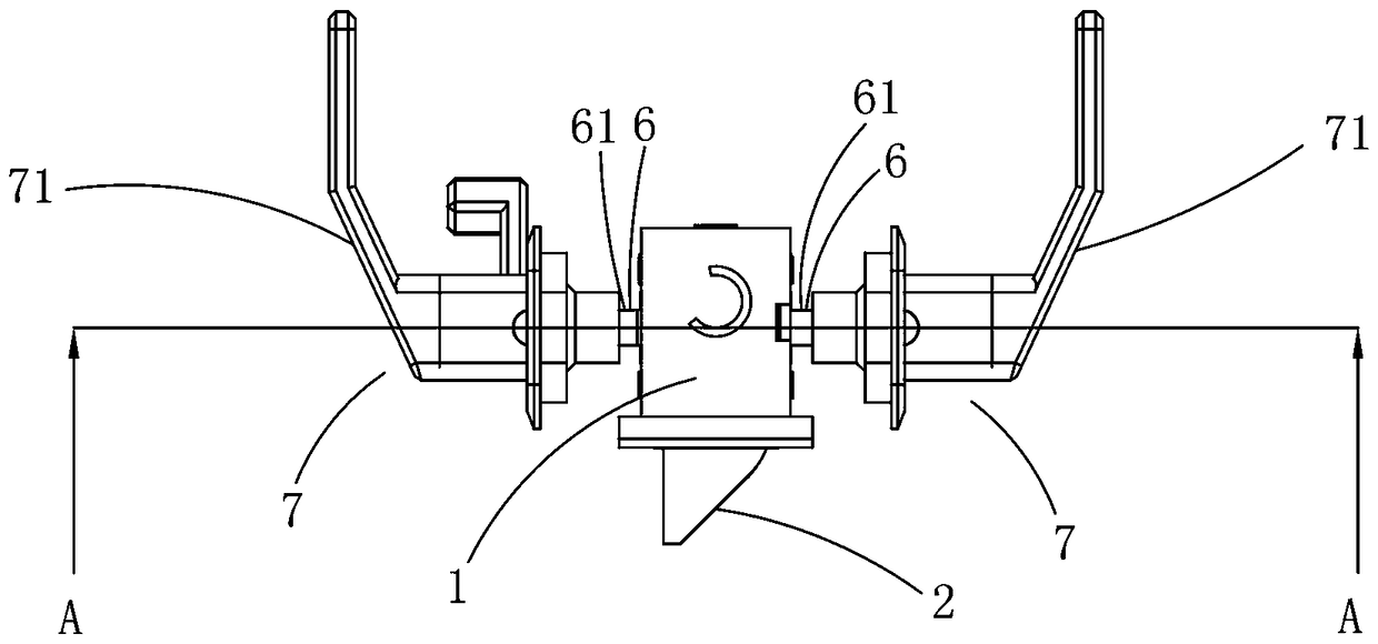
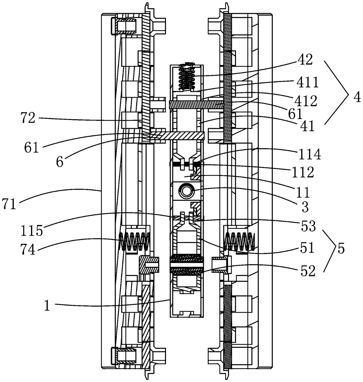
[0032] Example, combined with Figure 1 to Figure 11 As shown, an easy-to-open lockset includes a housing 1 , a deadbolt 2 disposed on the housing 1 , a deadbolt spring 3 , a first limiting component 4 and a second limiting component 5 .

[0033]The housing 1 is additionally provided with a deadbolt mounting frame 11. The deadbolt mounting frame 11 includes a front side plate 113, an upper side plate 114 and a lower side plate 115. The front side plate 113 has a dead bolt through hole 111. The side plate 114 and the lower side plate 115 respectively have guide holes 112 , the first limiting component 4 is located above the upper side plate 114 , and the second limiting component 5 is located below the lower side plate 115 .

[0034] The upper part of the inner end of the dead bolt 2 is provided with a first limiting chute 21, and the lower part of the inner end of the dead bolt 2 is provided with a second limiting chute 22. In 11, the outer end of dead bolt 2 extends out of t...


PUM


Abstract

The invention discloses a lock convenient to open. The lock comprises a shell and further comprises a spring bolt and a spring bolt spring which are arranged on the shell. The outer end of the springbolt extends out of the shell, the inner end of the spring bolt is arranged in the shell, and the inner end of the spring bolt abuts against the spring bolt spring. The lock is characterized in that the shell is further provided with a first limiting assembly and a second limiting assembly which abut against the inner end of the spring bolt in a movable manner so that the spring bolt can horizontally slide and can also swing front and back on the shell; a user removes front-back swinging limiting on the spring bolt through the first limiting assembly and the second limiting assembly, and the spring bolt can be set to be in a horizontal sliding and front-back swinging state; when the user conducts unlocking outside a door, force can be directly acted on a door body without waiting for contraction of the spring bolt into the lock body, the spring bolt horizontally slides while swinging, and the purpose of unlocking is achieved; and operation of the lock is extremely simple and convenient, and meanwhile, the integral structure is simple and reasonable.

Description

technical field [0001] The invention relates to a lock, in particular to a convenient open lock. Background technique [0002] The deadbolt of traditional locks can only expand and contract horizontally along the lock body (that is, the deadbolt can only slide horizontally on the housing, and cannot swing back and forth). It is necessary to reversely twist the handle until the deadbolt is completely retracted into the lock body, and then push the door body inward to realize the door opening operation. However, the unlocking operation of this kind of door body still has the following disadvantages: (1) because the deadbolt It cannot swing back and forth. When unlocking the door, the user needs to turn the direction of the handle accurately, and turn the handle in the opposite direction to the end position, so that the bolt completely exits the bolt hole of the door frame (that is, the bolt is completely retracted into the lock body). And by pushing the door body, the unlocki...

Claims


Application Information

Patent Timeline
Patent Type & Authority Applications(China)
IPC IPC(8): E05B15/10E05B15/00
CPCE05B15/00E05B15/102
Inventor 徐志克
Owner 中山市欧柏克五金制品有限公司
Learn More