Bridge deck filling equipment

An equipment and end face technology, applied in the field of bridge deck filling equipment, can solve the problems of affecting the efficiency of watering and filling, slowing down the filling progress, and large labor force, so as to reduce the amount of manual labor, improve the uniformity, and reduce the labor force.

Inactive Publication Date: 2018-09-14
陈亚利
View PDF0 Cites 2 Cited by
  • Summary
  • Abstract
  • Description
  • Claims
  • Application Information

AI Technical Summary

Problems solved by technology

[0002] In bridge road maintenance, the filling of the potholes on the bridge pavement is part of the daily work of the maintenance workers. Before the maintenance, the sand and gravel materials required for filling need to be mixed and then poured and filled. This operation process directly affects the Irrigation and filling efficiency. In traditional technology, manual stirring is generally used. The labor force is large and the speed is slow, which slows down the filling progress. There are also some irrigation devices that can be automatically stirred, but the cost of use is high and the operation is extremely complicated. , it is easy to splash on the bridge facilities during discharge, which makes it difficult to clean and cannot guarantee the cleanliness of the surrounding facilities. There are major disadvantages and it is difficult to meet the existing needs

Method used


Image

  • Bridge deck filling equipment
  • Bridge deck filling equipment
  • Bridge deck filling equipment

Examples


Embodiment Construction

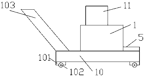
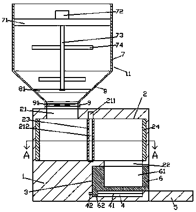
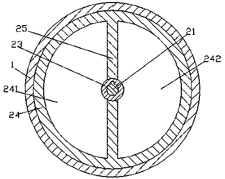
[0022] Such as Figure 1-Figure 7 As shown, a bridge deck filling device of the present invention includes a base plate 10, a round platform 1 arranged above the base plate 10, and a bucket 11 arranged above the round platform 1, and four corners of the bottom of the base plate 10 are provided with There is a corner post 101, the bottom of the corner post 101 is provided with rollers, the left side of the bottom plate 10 is fixedly connected with a handle 103, so as to realize the convenience of moving or carrying, the top end surface of the bottom plate 10 and the bottom end surface of the bucket bin 11 Fixedly connected, the bucket bin 11 includes a first bucket portion 7, a second bucket portion 8 arranged at the bottom of the first bucket portion 7, and a third bucket portion 9 arranged at the bottom of the second bucket portion 8, so The inside of the round platform 1 is provided with a first chamber 2, the top of the left side of the first chamber 2 is provided with a fi...


PUM


Abstract

The invention discloses bridge deck filling equipment. The bridge deck filling equipment comprises a bottom plate, a circular truncated cone arranged above the bottom plate, and a hopper arranged above the circular truncated cone, wherein corner columns are arranged at four corners at the bottom of the bottom plate; roller wheels are arranged at the bottom of the corner columns; a handle is fixedly connected to the left side end of the bottom plate; the end surface of the top of the bottom plate is fixedly connected with the end surface of the bottom of the hopper; the hopper comprises a firsthopper part, a second hopper part arranged at the bottom of the first hopper part and a third hopper part arranged at the bottom of the second hopper part; a first accommodating cavity is formed in the circular truncated cone; a first opening part communicated with the third hopper part is arranged on the top of the left side of the first accommodating cavity; a second opening part is arranged atthe bottom of the right side of the first accommodating cavity; a second accommodating cavity is formed in the circular truncated cone at the bottom of the second opening part; a sliding slot is formed in the circular truncated cone at the bottom of the second accommodating cavity; and a loop in rotary matching connection is arranged inside the first accommodating cavity. The bridge deck fillingequipment is simple in structure, automatic in control and convenient to operate, reduces the labor, reduces the manual labor amount, can automatically control stirring and discharge, and has relatively high cleanliness.

Description

technical field [0001] The invention relates to the technical field of bridge equipment, in particular to bridge deck filling equipment. Background technique [0002] In bridge road maintenance, the filling of the potholes on the bridge pavement is part of the daily work of the maintenance workers. Before the maintenance, the sand and gravel materials required for filling need to be mixed and then poured and filled. This operation process directly affects the Irrigation and filling efficiency. In traditional technology, manual stirring is generally used. The labor force is large and the speed is slow, which slows down the filling progress. There are also some irrigation devices that can be automatically stirred, but the cost of use is high and the operation is extremely complicated. , it is very easy to splash on the bridge facilities during discharge, which makes cleaning difficult and cannot guarantee the cleanliness of the surrounding facilities. There are major disadvant...

Claims


Application Information

Patent Timeline
Patent Type & Authority Applications(China)
IPC IPC(8): E01C23/10
CPCE01C23/10
Inventor 陈亚利
Owner 陈亚利
Why Eureka
Try Eureka