
Nailing workbench for plank processing

A workbench and nailing technology, which is applied to nailing tools, manufacturing tools, nailing tools, etc., can solve the problems of low labor intensity, high labor intensity, and poor transmission effect of reel-axle planks, and achieve low labor intensity. , the transmission effect is good

Inactive Publication Date: 2018-09-14
张美姣
View PDF0 Cites 8 Cited by
  • Summary
  • Abstract
  • Description
  • Claims
  • Application Information

AI Technical Summary

Problems solved by technology

[0004] In order to solve the above-mentioned problems, the present invention provides a nailing workbench for wood board processing, which can solve the problems of high labor intensity, inability to automatically fix the cable disc, and the problems of laying the shaft wood board on the cable disc. The disc cannot automatically control the rotation, the transmission effect of the disc shaft plank is poor, the action of nailing the disc shaft plank cannot be performed automatically, and the disc shaft plank cannot be squeezed when nailing; it can realize the automatic control of different sizes of cable discs. The function of supporting the rotation and automatically binding the plank on the cable disc has the advantages of low labor intensity, automatic fixation of the cable disc, automatic control of the rotation of the cable disc, good transmission effect of the plank on the disc shaft, and automatic alignment of the plank on the disc shaft It has the advantages of performing nailing action and squeezing the plank when nailing, etc.

Method used


Image

  • Nailing workbench for plank processing
  • Nailing workbench for plank processing
  • Nailing workbench for plank processing

Examples


Embodiment Construction

[0026] In order to make the technical means, creative features, goals and effects achieved by the present invention easy to understand, the present invention will be further described below in conjunction with specific illustrations. It should be noted that, in the case of no conflict, the embodiments in the present application and the features in the embodiments can be combined with each other.

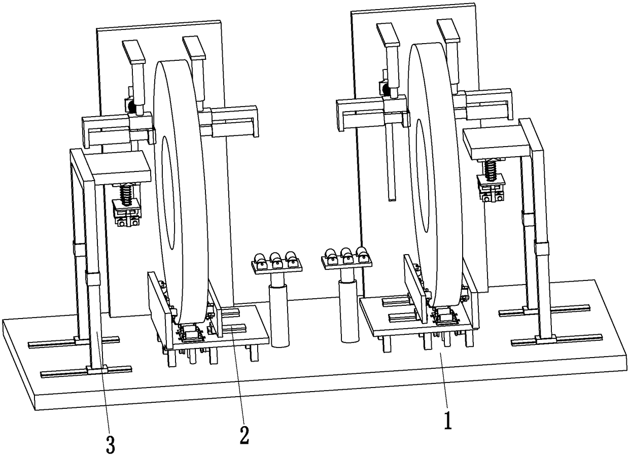
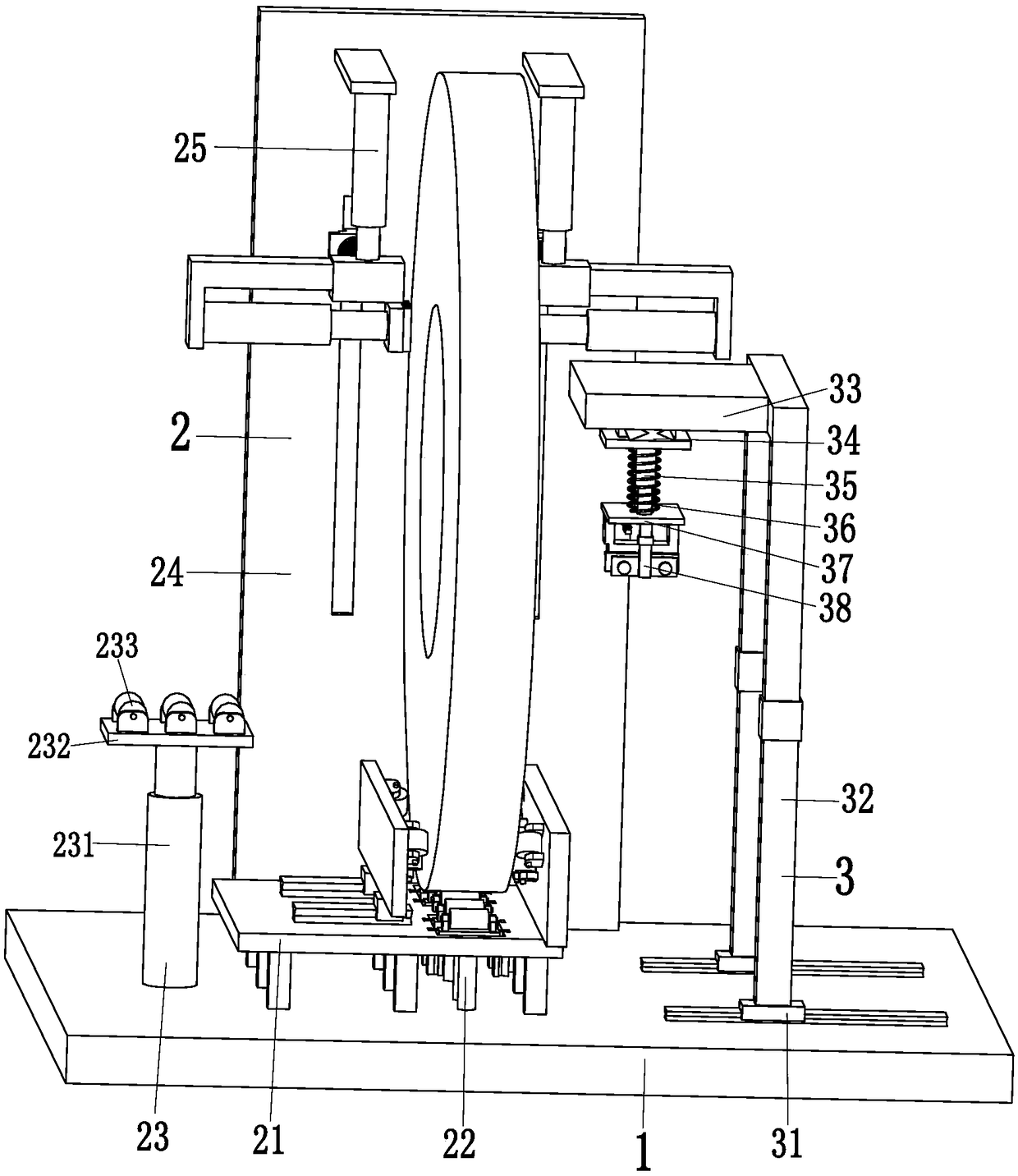
[0027] Such as Figure 1 to Figure 5 As shown, a nailing workbench for wood processing includes a support base plate 1, two positioning devices 2 and a binding device 3, and two positioning devices 2 are symmetrically installed on the top of the support base plate 1, and each positioning device 2 are provided with a binding device 3 on the outside, and the binding device 3 is installed on the top of the support base plate 1.

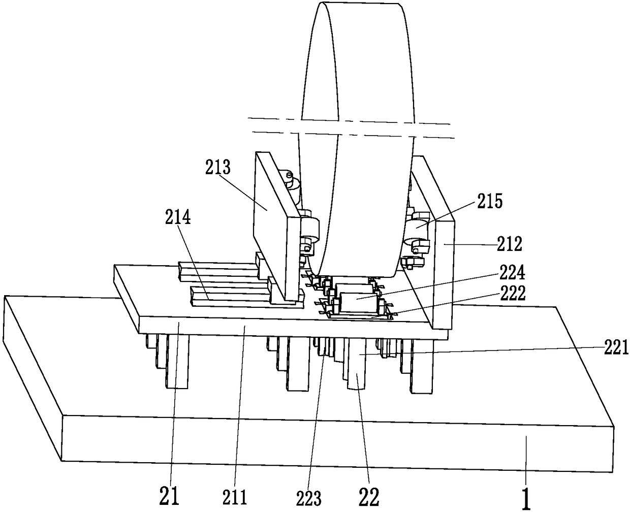
[0028] The positioning device 2 includes a fitting mechanism 21, two sets of supporting mechanisms 22, a transmission mechanism 23, a fixed side plate 24 and ...


PUM


Abstract

The invention relates to a nailing workbench for plank processing. The nailing workbench comprises a supporting bottom plate, two positioning devices and nailing devices. The two positioning devices are symmetrically installed on the top of the supporting bottom plate, the outer side of each positioning device is provided with one nailing device, the nailing devices are installed on the top of thesupporting bottom plate, and each positioning device comprises an adhering mechanism, two sets of supporting mechanisms, a conveying mechanism, a fixed side plate and a moving mechanism. The problemsthat when disc shaft planks are laid for a cable disc at present, the labor intensity is large, the cable disc cannot be automatically fixed, rotation of the cable disc cannot be automatically controlled, the disc shaft plank conveying effect is poor, nail feeding action cannot be automatically carried out on the disc shaft planks, and the disc shaft planks cannot be squeezed during nail feedingare solved, and the functions that cable discs with different sizes can be automatically supported and rotated and the disc shaft planks are automatically nailed to the cable disc are achieved.

Description

technical field [0001] The invention relates to the technical field of wood board processing, in particular to a nailing workbench for wood board processing. Background technique [0002] The cable reel is a reel with the function of winding wires and cables. The large cable reel is basically a wooden reel. Large cables are widely used in oil fields, mines, construction, machinery manufacturing units, scientific research units and many other industries. Factors such as low cost and simple manufacturing process are widely used, and the coil shaft plank is the most important part in the cable coil. [0003] The production of cable reels is basically carried out manually. First, two hollow cable discs are made, and the two cable discs are fixed. The nail gun nails the reel plank on the hollow surface of the cable disc, and finally manually rotates the cable disc to complete the nailing of the cable reel. The reel is mainly used to wind up the cable. The existing problems are ...

Claims


Application Information

Patent Timeline
IPC IPC(8): B27F7/02
CPCB27F7/02
Inventor 张美姣
Owner 张美姣
Learn More