
Battery thermostat for multi-rotor unmanned aerial vehicle

A technology of multi-rotor drones and constant temperature equipment, applied in the field of drones, can solve problems such as unstable power supply, drones falling, etc., and achieve the effect of reducing heat loss

Active Publication Date: 2018-09-07
倪惠芳
View PDF3 Cites 1 Cited by
  • Summary
  • Abstract
  • Description
  • Claims
  • Application Information

AI Technical Summary

Problems solved by technology

[0002] UAV is an unmanned aircraft controlled by radio remote control equipment and its own program control device. There is no cockpit on board, but it is equipped with autopilot, program control device and other equipment. Radar and other equipment, for tracking, positioning, remote control, telemetry and digital transmission, can take off like an ordinary plane under radio control or launch it with a booster rocket, and can also be brought into the air by the mother plane. However, its battery is due to Under the influence of low temperature, the phenomenon of unstable power supply often occurs, which makes the drone fall accidently. Therefore, we propose a battery constant temperature device for multi-rotor drones to solve the above problems.

Method used


Image

  • Battery thermostat for multi-rotor unmanned aerial vehicle
  • Battery thermostat for multi-rotor unmanned aerial vehicle
  • Battery thermostat for multi-rotor unmanned aerial vehicle

Examples


Embodiment Construction

[0017] The following will clearly and completely describe the technical solutions in the embodiments of the present invention with reference to the accompanying drawings in the embodiments of the present invention. Obviously, the described embodiments are only some, not all, embodiments of the present invention. Based on the embodiments of the present invention, all other embodiments obtained by persons of ordinary skill in the art without making creative efforts belong to the protection scope of the present invention.

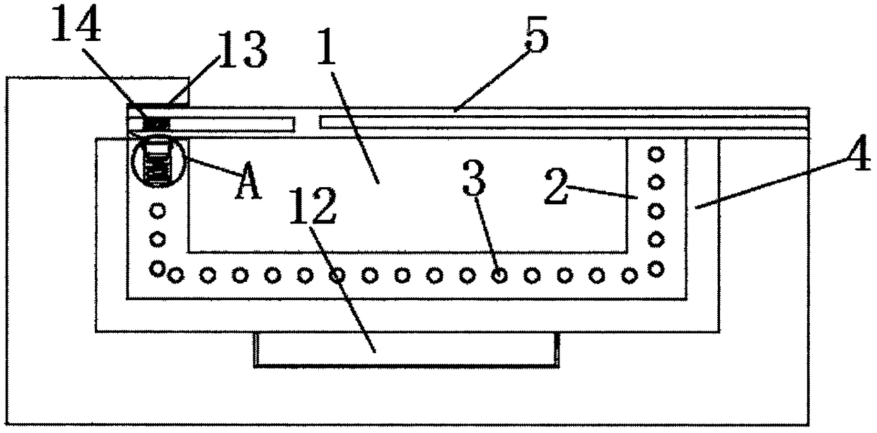
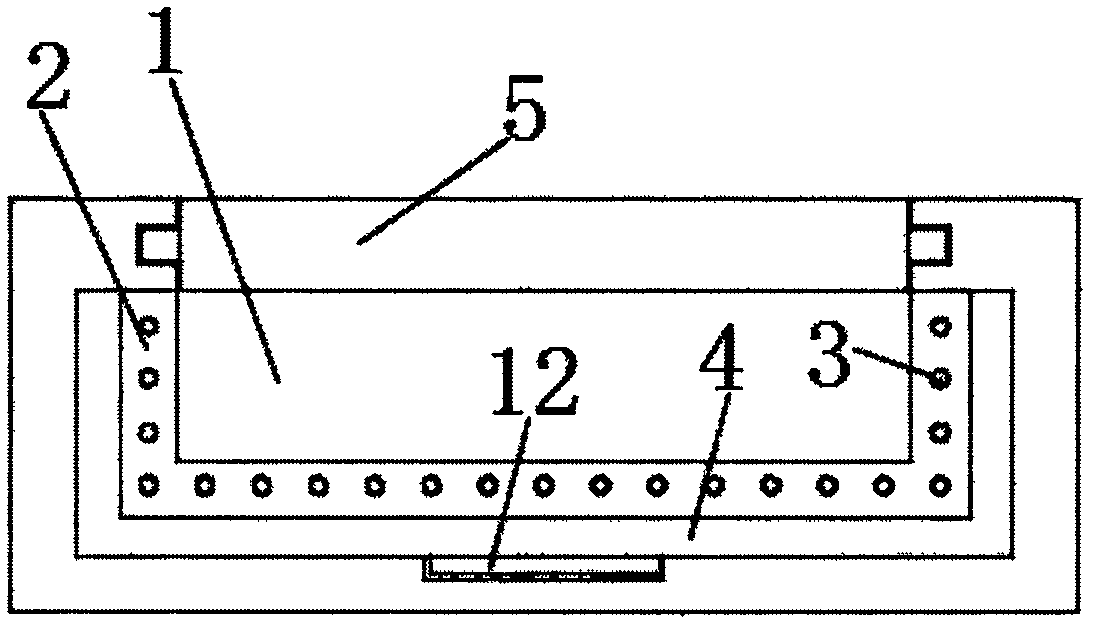
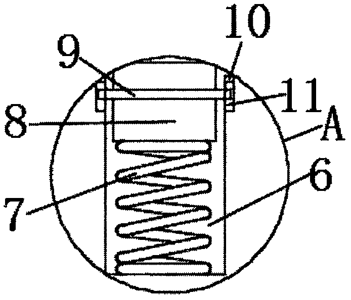
[0018] see Figure 1-3 , the present invention provides a technical solution: a multi-rotor UAV battery constant temperature equipment, including UAV battery tank 1, the bottom of the UAV battery tank 1 is provided with a circular groove, and the circular groove is provided with A heating plate 12 matched with the circular groove, and the side wall of the heating plate 12 is fixedly connected with the groove wall of the circular groove. The upper side of the h...


PUM


Abstract

The invention discloses a battery thermostat for a multi-rotor unmanned aerial vehicle. The battery thermostat comprises an unmanned aerial vehicle battery tank, a circular groove is arranged in the tank bottom of the unmanned aerial vehicle battery tank, a heating plate matched with the circular groove is arranged in the circular groove, the sidewall of the heating plate is fixedly connected withthe groove wall of the circular groove, a U-shaped heat conduction plate is arranged at the upper side of the heating plate, the sidewall of the U-shaped heat conduction plate is fixedly connected with the tank wall of the unmanned aerial vehicle battery tank, the lower side of the U-shaped heat conduction plate is laminated to the upper side of the heating plate, a U-shaped heat insulation plateis arranged at the inner side of the U-shaped heat conduction plate, the outer side of the U-shaped heat insulation plate is fixedly connected with the inner side of the U-shaped heat conduction plate, a horizontal baffle plate is arranged at the upper side of the unmanned aerial vehicle battery tank, the front sidewall and the rear sidewall of the unmanned aerial vehicle battery tank are provided with horizontal sliding slots, the inner sides of sliding blocks are fixedly connected with two sides of the baffle plate, and the upper side of the front end of the baffle plate and the upper wallof the unmanned aerial vehicle battery tank are provided with jagged projections. The battery thermostat makes the temperature of the unmanned aerial vehicle battery keep constant.

Description

technical field [0001] The invention relates to the field of unmanned aerial vehicles, in particular to a battery constant temperature device for a multi-rotor unmanned aerial vehicle. Background technique [0002] UAV is an unmanned aircraft controlled by radio remote control equipment and its own program control device. There is no cockpit on board, but it is equipped with autopilot, program control device and other equipment. Radar and other equipment, for tracking, positioning, remote control, telemetry and digital transmission, can take off like an ordinary plane under radio control or launch it with a booster rocket, and can also be brought into the air by the mother plane. However, its battery is due to Under the influence of low temperature, the power supply is often unstable, which makes the UAV fall accidents. Therefore, we propose a battery constant temperature device for multi-rotor UAVs to solve the above problems. Contents of the invention [0003] The purpo...

Claims


Application Information

Patent Timeline
Patent Type & Authority Applications(China)
IPC IPC(8): H01M10/615H01M10/625H01M10/65H01M10/6554H01M10/658H01M2/10H01M50/249
CPCH01M10/615H01M10/625H01M10/65H01M10/6554H01M10/658H01M2220/20H01M50/20B64U50/19Y02E60/10
Inventor 倪惠芳
Owner 倪惠芳
Learn More