A method for detecting the quality of contact hole making
A detection method and contact technology, applied in the direction of measuring devices, instruments, etc., can solve the problems affecting the accuracy and efficiency of hole measurement, low detection accuracy, heavy workload, etc., achieve less test parameters, simple calculation method, and improve accuracy Effect
- Summary
- Abstract
- Description
- Claims
- Application Information
AI Technical Summary
Problems solved by technology
Method used
Image
Examples
Embodiment 1
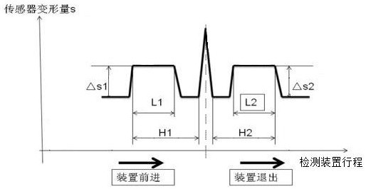
[0030]A method for detecting the quality of contact-type hole-making. The quality of the hole 3 to be measured is detected by the detection device extending into the hole 3 to be measured, and the stroke value and deformation amount of the detection device inserted into the hole 3 to be measured are recorded, which are used to calculate the hole to be measured. Measuring the diameter of the hole 3, the depth of the hole, the depth of the spot spot, and the radius of the spot spot; the detection device includes a detection unit, a connector 13, a first bushing 1, a second bushing 4, and a mounting seat 6, and the detection unit includes The probe 17, probe 16, conductor 12 and displacement sensor 18 are arranged in the connector 13 in order from left to right; the two ends of the outer side of the connector 13 are respectively connected to the first bush 1 and the second bush 4 , the first bushing 1 is connected to the conductor 12 through the connector 13, and the first bushing...
Embodiment 2
[0033] This embodiment is further optimized on the basis of embodiment 1, as figure 2 As shown, a compression spring 2 is arranged between the first bush 1 and the second bush 4, so that it can return to its original position after being contacted by force; the second bush 4 can slide relative to the mounting seat 6, and the The mounting seat 6 is provided with an elliptical hole, and the second bushing 4 is correspondingly provided with a round hole. The mounting seat 6 and the second bushing 4 are connected by a cylindrical pin 5, and the cylindrical pin 5 passes through the ellipse in turn. holes and round holes; the cylindrical pin 5 can move in the oval hole, so that the second bushing 4 can slide in the axial direction of the mounting seat 6;
[0034] Such as image 3 As shown, the side wall of the free end of the probe 17 is symmetrically provided with a through hole, the through hole is provided with a deformable block 9, one end of the deformable block 9 passes thro...
Embodiment 3
[0041] This embodiment is further optimized on the basis of Embodiment 2. The detection process of the detection device entering and exiting the hole 3 to be measured is mirrored, and the deformation amount of the deformable block 9 passing through the hole 3 to be measured is The deformable block 9 is completely compressed by the wall of the hole 3 to be measured to the stroke value of the detection device when the first bush 1 is just in contact with the hole 3 to be measured The stroke parameters of the detection device movement during the passage of the deformable block 9 through the hole 3 to be measured
[0042] In the detection method, the probe 17 is inserted into the hole 3 to be measured along the axial direction of the hole 3 to be measured until the first bush 1 cannot move relative to the connector 13, then the detection device returns to the hole 3 to be measured according to the opposite route, The displacement sensor 18 records the stroke value H2 of the de...
PUM
 Abstract
Description
Claims
Application Information
 - R&D
- Intellectual Property
- Life Sciences
- Materials
- Tech Scout
- Unparalleled Data Quality
- Higher Quality Content
- 60% Fewer Hallucinations
Browse by: Latest US Patents, China's latest patents, Technical Efficacy Thesaurus, Application Domain, Technology Topic, Popular Technical Reports.
© 2025 PatSnap. All rights reserved.Legal|Privacy policy|Modern Slavery Act Transparency Statement|Sitemap|About US| Contact US: help@patsnap.com


