
Spline shaft mechanism for agricultural machine and low in use cost

A technology for agricultural machinery and spline shafts, applied in mechanical equipment, shaft couplings, rigid shaft couplings, etc., can solve the problem of unbalanced force on spline shafts and bushings, easy wear of spline shafts, and limited protrusions. Ring wear and other problems, achieve the effect of force balance, increase service life and reduce use cost

Inactive Publication Date: 2018-08-31
姚岚
View PDF1 Cites 2 Cited by
  • Summary
  • Abstract
  • Description
  • Claims
  • Application Information

AI Technical Summary

Problems solved by technology

[0003] 1. The surface of the spline shaft in the device is easy to wear, the service life is short, it needs to be replaced regularly, and the use cost is high;
[0004] 2. The limit convex ring is easy to be worn by the interference of the shaft sleeve. When the limit convex ring is worn out, the entire spline shaft needs to be replaced, and the shaft sleeve is easy to shake;
[0005] 3. There is only one keyway on the spline shaft, the force between the spline shaft and the sleeve is unbalanced, the wear between the two is serious, and the service life is low

Method used


Image

  • Spline shaft mechanism for agricultural machine and low in use cost
  • Spline shaft mechanism for agricultural machine and low in use cost
  • Spline shaft mechanism for agricultural machine and low in use cost

Examples


Embodiment Construction

[0027] In order to make the object, technical solution and advantages of the present invention clearer, the present invention will be further described in detail below through the accompanying drawings and embodiments. However, it should be understood that the specific embodiments described here are only used to explain the present invention, and are not intended to limit the scope of the present invention.

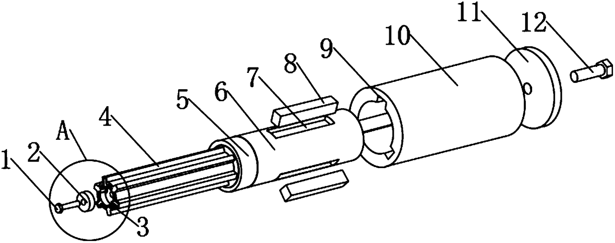
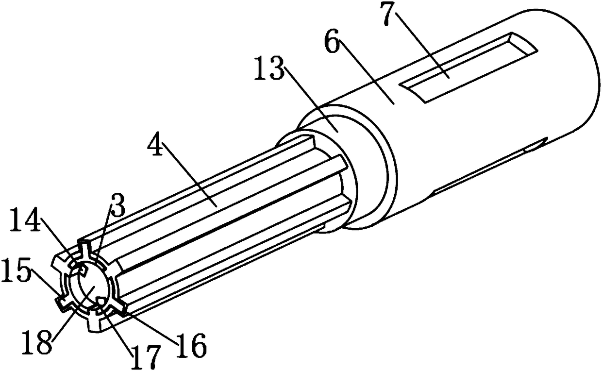
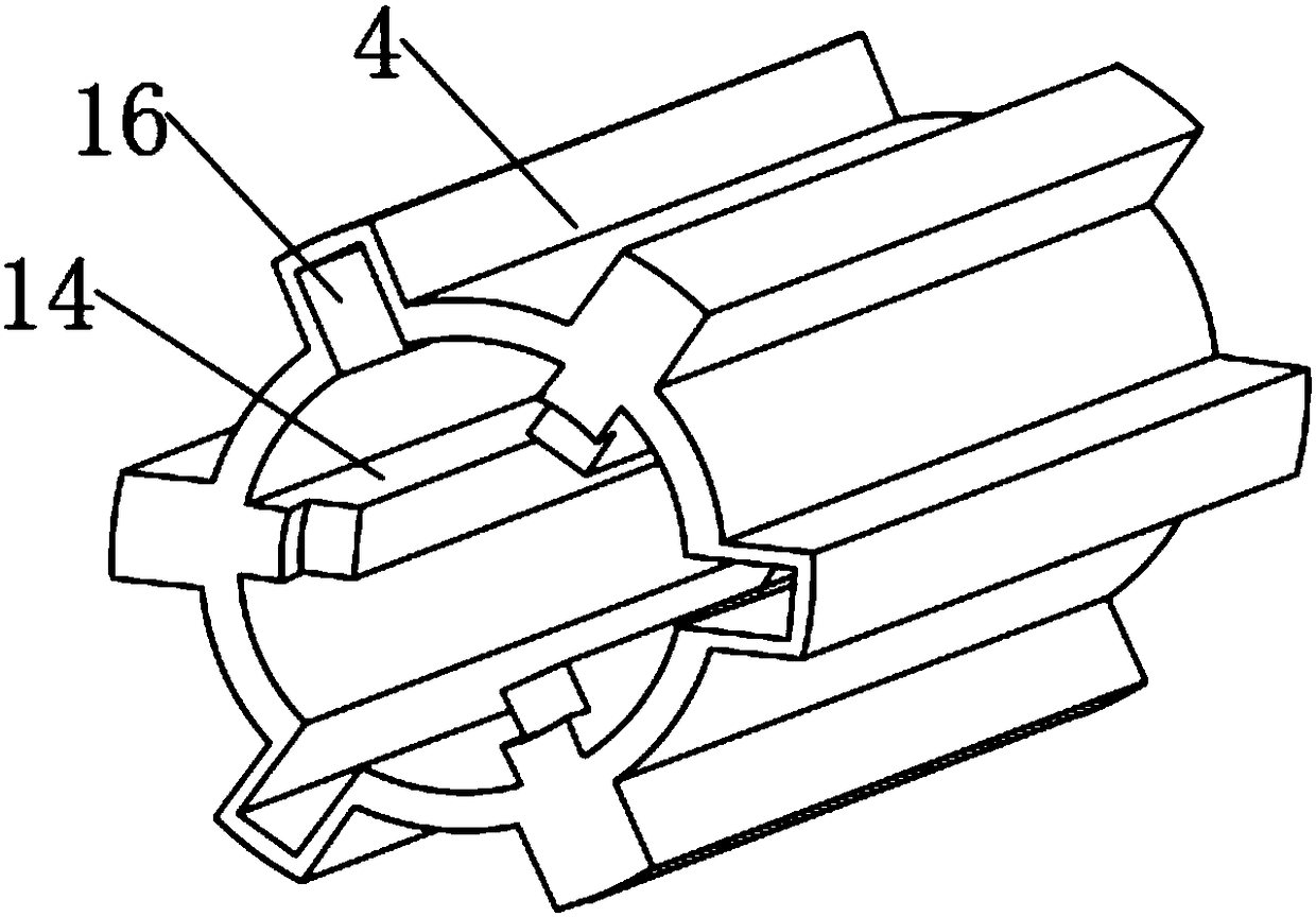
[0028] see Figure 1-4 , the present invention provides a technical solution: a low-cost spline shaft mechanism for agricultural machinery, including: a spline shaft 3, a spline sleeve 4, a connecting section 6 and a shaft sleeve 10; 4 sets of spline sleeves Set on the outer ring of the spline shaft 3, the outer ring of the spline shaft 3 is fixed with three spline outer teeth 15 in a circular array, and the inner ring of the spline shaft 3 is provided with three teeth in a circular array. Spline outer ring tooth grooves 17, three spline outer ring teeth 15 and three spl...


PUM


Abstract

The invention discloses a spline shaft mechanism for an agricultural machine and low in use cost. The spline shaft mechanism comprises a spline shaft, a spline shaft sleeve, a connecting segment and ashaft sleeve. The spline shaft sleeve is arranged on the outer ring of the spline shaft in a sleeving manner. Three spline outer teeth are fixedly arranged on the outer ring of the spline shaft in around array shape. Three spline outer ring tooth grooves are formed in the inner ring of the spline shaft in a round array shape. The surface of the spline shaft is sleeved with the spline shaft sleeve, the spline shaft sleeve is fixedly limited on the spline shaft through a fixing ring on the left end, the spline shaft sleeve replaces the spline shaft to be in contact with an outer device, wear of the spline shaft is reduced, and the service life of the spline shaft is prolonged; when damaged, the spline shaft sleeve can be independently replaced, and the use cost is reduced; a limiting convex ring is connected to an outer ring threaded groove in the left end of the connecting segment through threaded fit, demounting and mounting are convenient, and the aim of abutting against the shaft sleeve is achieved; and the limiting convex ring and the connecting segment are designed independently, replacement is convenient, the defect that the overall body needs to be replaced during wear is avoided, and the use cost is reduced.

Description

technical field [0001] The invention relates to the technical field of agricultural machinery, in particular to a spline shaft mechanism for agricultural machinery with low use cost. Background technique [0002] The patent application number is: 201410742023.X, and the patent name is: A spline shaft mechanism for agricultural machinery. One end of the sleeve is provided with a cover plate, and the cover plate is provided with a spline shaft fixed to the spline shaft by bolts. The through hole on the device is convenient and quick to install, and has good firmness and good transmission effect. It is especially suitable for agricultural machinery, but it still has the following disadvantages in the actual use process: [0003] 1. The surface of the spline shaft in the device is easy to wear, the service life is short, it needs to be replaced regularly, and the use cost is high; [0004] 2. The limit convex ring is easy to be worn by the interference of the shaft sleeve. When...

Claims


Application Information

Patent Timeline
IPC IPC(8): F16D1/10
CPCF16D1/10F16D2001/103
Inventor 姚岚
Owner 姚岚
Learn More