Cutting knife for garden brush cutter
A technology for brush cutters and gardens, which is applied in the field of cutting knives for garden brush cutters, and can solve the problems that the blades are easy to hurt the user, the blades are broken, and the blades are not elastic.
- Summary
- Abstract
- Description
- Claims
- Application Information
AI Technical Summary
Problems solved by technology
Method used
Image
Examples
Embodiment 1
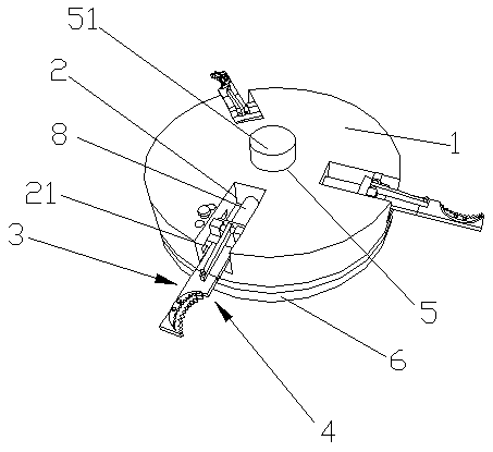
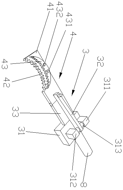
[0022] like Figure 1-2 Shown, a kind of cutting knife for garden brush cutter of the present invention comprises main cutter disc 1, and main cutter disc 1 is a disc-shaped structure, and main cutter disc 1 is provided with several cutter grooves 2, and the cutter The inner wall of the groove 2 is oppositely provided with a cutter chute 21, a plurality of cutters 3 are movable in the cutter chute 21, and the cutter 3 includes a cutter seat 31, and the cutter seat 31 is movably arranged in the cutter chute 21 , the cutter seat 31 is provided with a first fixed block 311 and a second fixed block 312, a rotating shaft 313 is arranged between the first fixed block 311 and the second fixed block 312, and the rotating shaft 313 is provided with an adjusting rod 32, the cutter Seat 31 is also provided with fixed plate 33, and an end of fixed plate 33 is fixedly connected with cutter holder 31, and the other end of fixed plate 33 is hinged to cut blade body 4, and an end of adjusting...
Embodiment 2
[0024]The main cutter head 1 is a disc-shaped structure, and the main cutter head 1 is provided with some cutter grooves 2, and the inner wall of the cutter groove 2 is oppositely provided with a cutter chute 21, and the cutter chute 21 is movable to be provided with Some cutters 3, cutter 3 comprises cutter holder 31, and cutter holder 31 is movably arranged in cutter chute 21, and cutter holder 31 is provided with first fixed block 311 and second fixed block 312, the first fixed block 31 A rotating shaft 313 is arranged between the block 311 and the second fixed block 312, and an adjusting rod 32 is arranged on the rotating shaft 313, and a fixed plate 33 is also provided on the cutter seat 31, and one end of the fixed plate 33 is fixedly connected with the cutter seat 31 , the other end of the fixed plate 33 is hinged to the cutting blade body 4, one end of the adjusting rod 32 is movably connected to the rotating shaft 313, the other end of the adjusting rod 32 is movably c...
PUM
 Abstract
Description
Claims
Application Information
 - Generate Ideas
- Intellectual Property
- Life Sciences
- Materials
- Tech Scout
- Unparalleled Data Quality
- Higher Quality Content
- 60% Fewer Hallucinations
Browse by: Latest US Patents, China's latest patents, Technical Efficacy Thesaurus, Application Domain, Technology Topic, Popular Technical Reports.
© 2025 PatSnap. All rights reserved.Legal|Privacy policy|Modern Slavery Act Transparency Statement|Sitemap|About US| Contact US: help@patsnap.com


