Air cooling device for automobile hat and coat stand fiberglass board production line

A technology of an air cooling device and a coat rack, which is applied in the field of auto parts production, can solve the problem that the air deflector is not easy to maintain, and achieve the effects of simple structure, sensitive operation and good cooling effect.

Pending Publication Date: 2018-08-24
宁波尚唯汽车饰件有限公司
View PDF1 Cites 1 Cited by
  • Summary
  • Abstract
  • Description
  • Claims
  • Application Information

AI Technical Summary

Problems solved by technology

[0005] Both of the above two air-cooling devices can achieve air-cooling of glass fiber boards, but they are all one-piece structures. The air-cooling chamber part, especially the air deflector part, is not easy to maintain, and the entire equipment needs to be disassembled. In terms of

Method used


Image

  • Air cooling device for automobile hat and coat stand fiberglass board production line
  • Air cooling device for automobile hat and coat stand fiberglass board production line
  • Air cooling device for automobile hat and coat stand fiberglass board production line

Examples


Embodiment 1

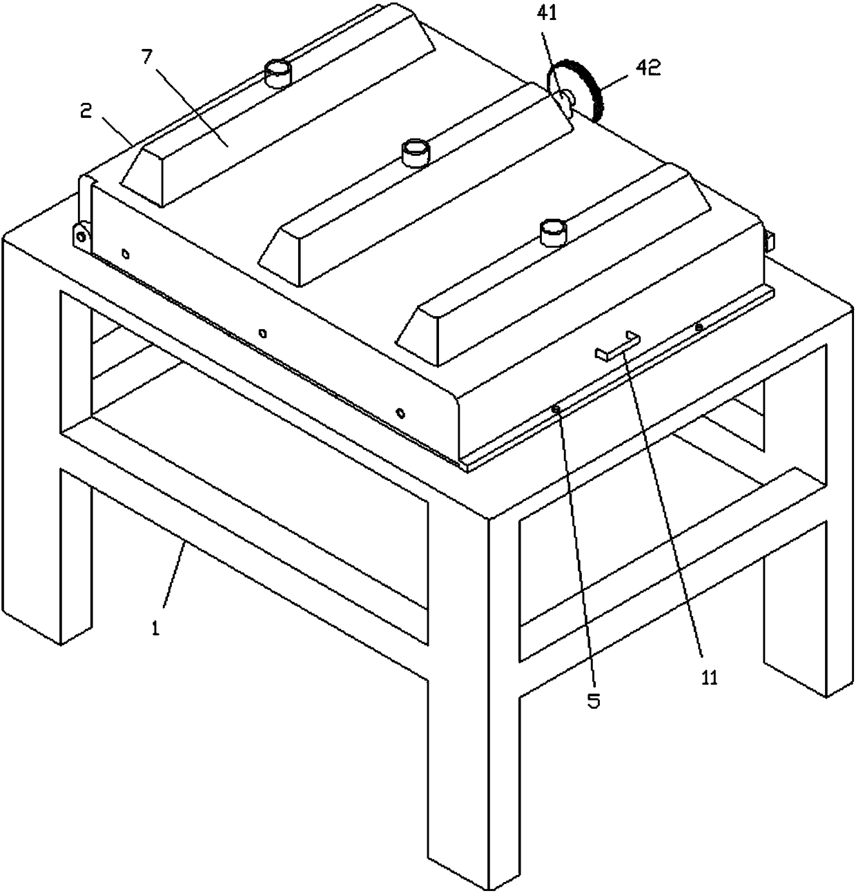
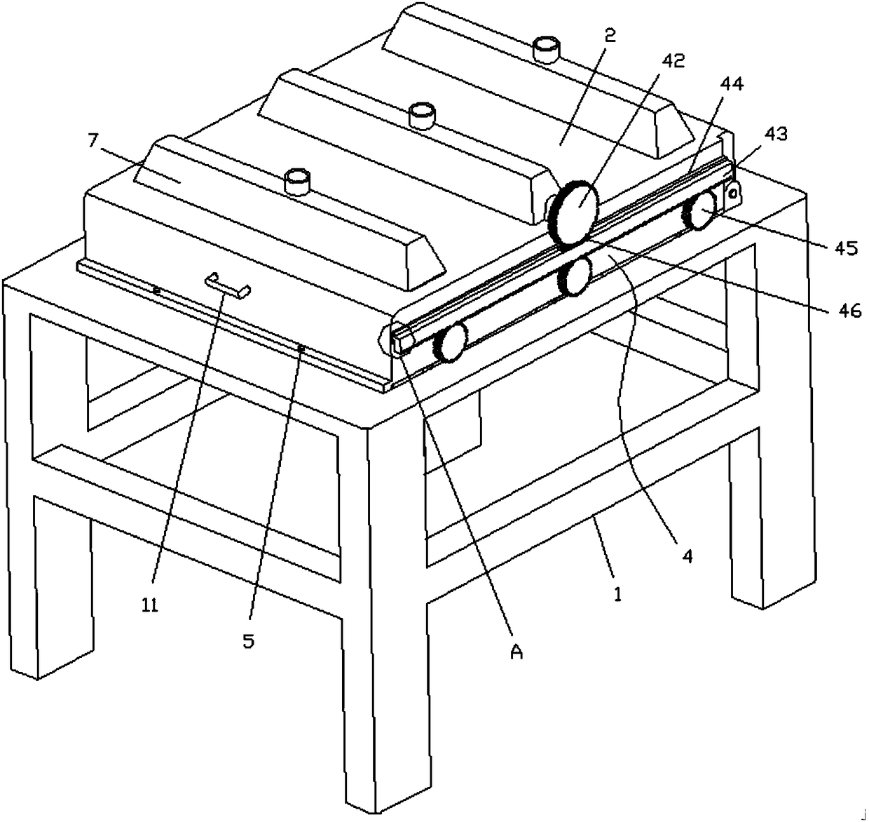
[0023] Such as Figure 1 to Figure 5 Shown, a kind of air-cooling device for the production line of glass fiberboard of automobile coat rack, comprises air-cooling frame 1, air-cooling chamber 2, wind deflector 3 and changing assembly 4, and one end of described air-cooling chamber 2 is hinged on One side of the air-cooled frame 1, the other end is connected with the air-cooled frame 1 by bolts 5, and the bottom of the air-cooled chamber 2 is provided with several air outlets 6, and the air outlet 6 is rotatably connected with the The wind deflector 3, the wind deflector 3 is connected to both sides of the air-cooled chamber 2 through the rotating shaft, and the top of the air-cooled chamber 2 is provided with an air inlet 54;

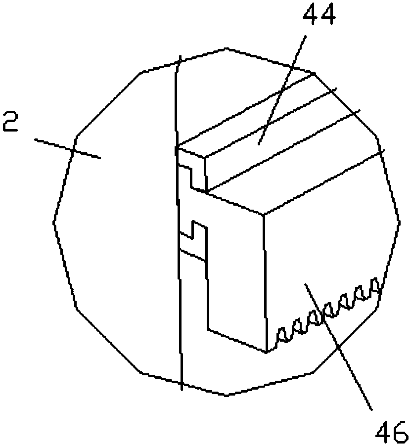
[0024] The direction changing assembly 4 includes a servo motor 41, a driving gear 42, a rack 43, a chute 44 and a driven gear 45. The servo motor 41 is installed on the side of the air cooling chamber 2, and the rack 43 is slidably connected to the ai...

Embodiment 2

[0029] Such as Figure 1 to Figure 4 Shown, a kind of air-cooling device for the production line of glass fiberboard of automobile coat rack, comprises air-cooling frame 1, air-cooling chamber 2, wind deflector 3 and changing assembly 4, and one end of described air-cooling chamber 2 is hinged on One side of the air-cooled frame 1, the other end is connected with the air-cooled frame 1 by bolts 5, and the bottom of the air-cooled chamber 2 is provided with several air outlets 6, and the air outlet 6 is rotatably connected with the The wind deflector 3, the wind deflector 3 is connected to both sides of the air-cooled chamber 2 through the rotating shaft, and the top of the air-cooled chamber 2 is provided with an air inlet 54;

[0030] The direction changing assembly 4 includes a servo motor 41, a driving gear 42, a rack 43, a chute 44 and a driven gear 45. The servo motor 41 is installed on the side of the air cooling chamber 2, and the rack 43 is slidably connected to the ai...


PUM


Abstract

The invention discloses an air cooling device for an automobile hat and coat stand fiberglass board production line, and relates to the technical field of automobile part production. The air cooling device comprises an air cooling rack, an air cooling chamber, air deflectors and a turning component, one end of the air cooling chamber is hinged to one side of the air cooling rack, the other end ofthe air cooling chamber is connected with the air cooling rack in a threaded manner, a plurality of exhaust outlets are formed in the bottom of the air cooling chamber, the air deflectors are rotatably connected at the exhaust outlets and rotatably connected on two sides of the air cooling chamber through rotating shafts, and an air inlet is formed in the top of the air cooling chamber. Accordingto the air cooling device, the air cooling chamber independently serves as a whole and can be lifted a certain angle when maintenance is needed, so that the air cooling chamber is conveniently maintained by a worker, air cooling effect is improved, the air deflectors are rotatable, angles of the air deflectors are changed under driving of the turning component, so that an air direction is changed,and better cooling effects are achieved.

Description

technical field [0001] The invention relates to the technical field of auto parts production, in particular to an air cooling device for a glass fiber board production line of an auto coat rack. Background technique [0002] There are many parts included in the car, such as a car coat rack. During the production process of the car coat rack, it is basically cooled by blowing, but generally it is cooled by an ordinary electric fan. Although this method is convenient to use, in the cooling process, the car coat rack dissipates heat unevenly, which is easy to deform and affects the product quality. Therefore need a kind of air cooling device that can have good use effect on the market. [0003] Chinese Patent Publication No. CN205735732U discloses an air-cooling device for a glass fiber board production line of an automobile coat rack, including a support frame, on which a transmission chain is installed, and an air guide groove is arranged above the transmission chain, and th...

Claims


Application Information

Patent Timeline
Patent Type & Authority Applications(China)
IPC IPC(8): B29C35/16B29L31/30
CPCB29C35/16B29C2035/1666B29L2031/30
Inventor 李嘉明鲁伟刘小康
Owner 宁波尚唯汽车饰件有限公司
Why Eureka
Try Eureka