A tripod for engineering supervision
A tripod and supervision technology, which is applied in the field of tripods, can solve the problems of affecting the accuracy of surveying and mapping, the decline of surveying and mapping instruments, and the inability to be stuck on the ground, so as to achieve the effect of ensuring the accuracy of surveying and mapping
- Summary
- Abstract
- Description
- Claims
- Application Information
AI Technical Summary
Problems solved by technology
Method used
Image

Examples
Embodiment 1
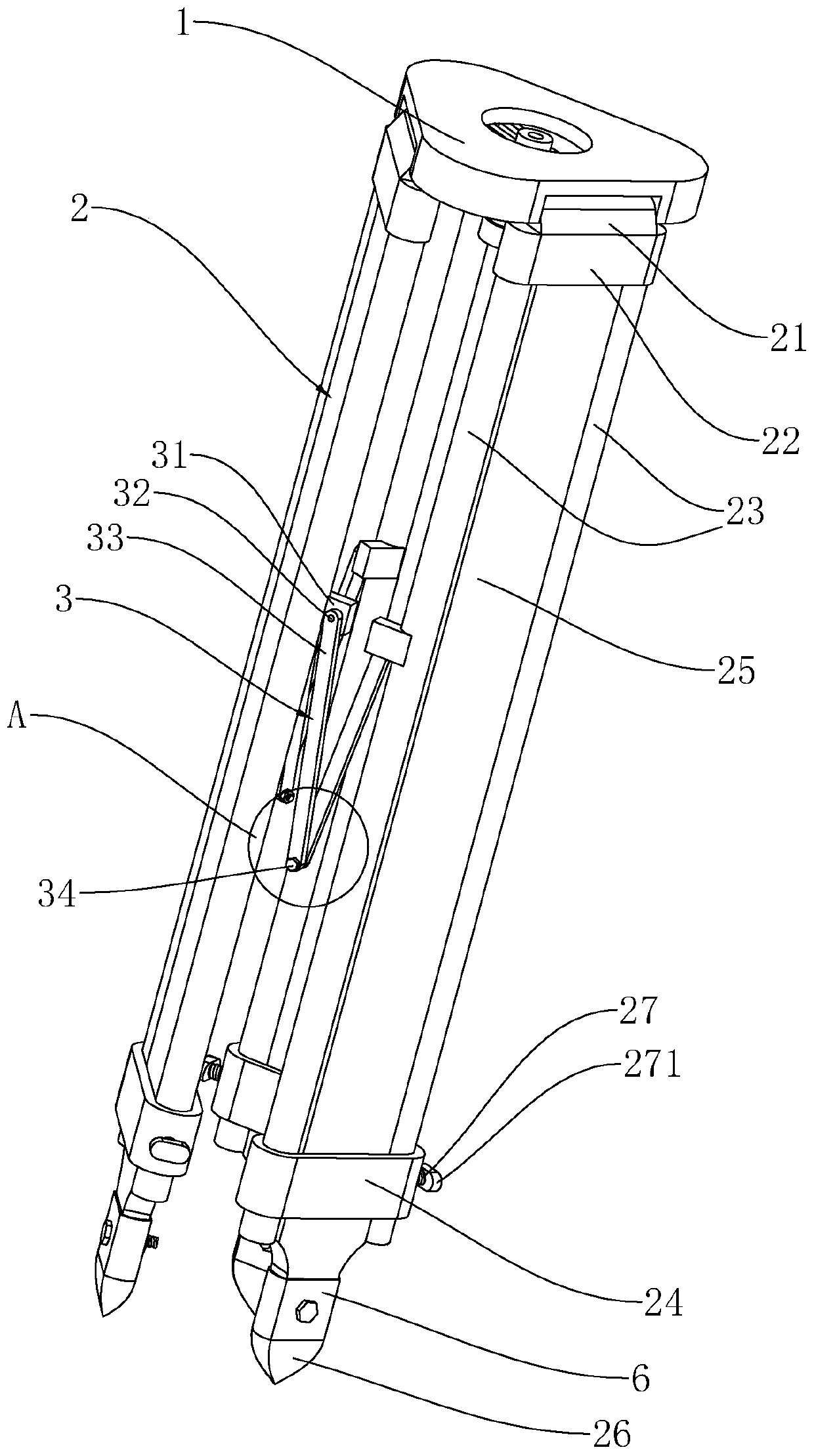
[0041] A kind of tripod for engineering supervision, such as figure 1 As shown, it includes a mounting platform 1 for fixing surveying and mapping instruments. The mounting platform 1 is triangular in shape and has length-adjustable legs 2 hinged on each side below.
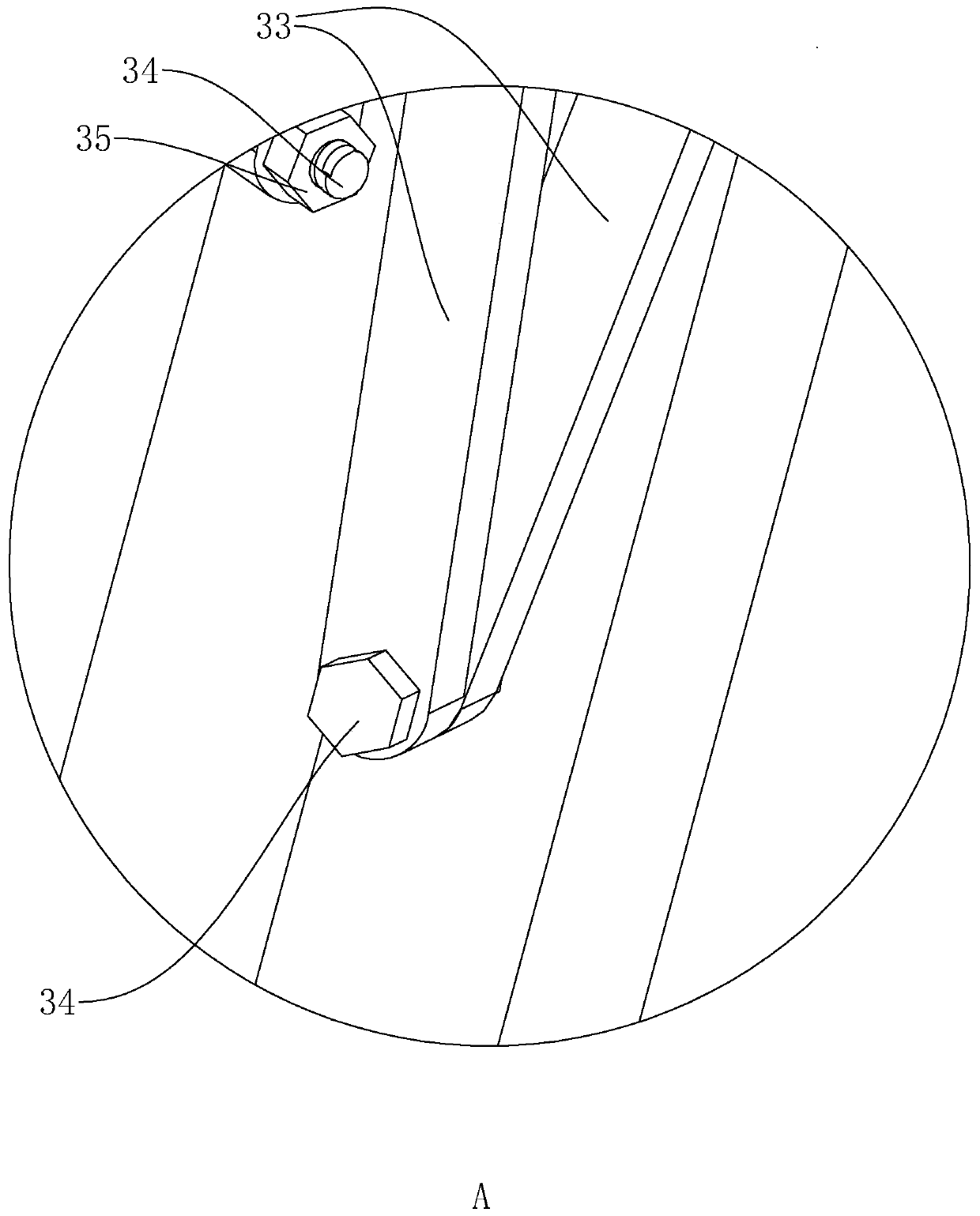
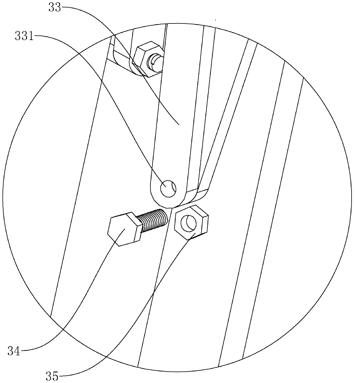
[0042] like figure 1 , figure 2As shown, two adjacent legs 2 are connected by a fixing device 3. The fixing device 3 includes a fixed block 31 fixedly connected with the legs 2. The fixed block 31 is fixedly connected with a rotating rod 32, and the rotating rod 32 is connected with a connecting bar 33 in rotation. . The ends of two adjacent connecting bars 33 away from the rotating rod 32 are jointly pierced with fixing bolts 34 . The connecting bars 33 can rotate around the axis of the fixing bolts 34 , so that the included angle between the two connecting bars 33 can be changed, so that the supporting foot 2 can rotate relative to the mounting table 1 .
[0043] like figure 2 , image 3 As shown, the h...
Embodiment 2
[0051] like Figure 7 , Figure 8 As shown, the difference from the first embodiment is that the support part 26 includes a connection plate 41 for fixed connection with the connection sleeve 6 . The side of the connecting plate 41 away from the sliding plate 25 is fixedly connected to the first hinged seat 42 , the first hinged seat 42 is hinged to the second hinged seat 44 via the hinged shaft 43 , and the second hinged seat 44 is fixedly connected to the flat plate 45 . The hinge axis 43 axis is parallel to the rotation axis 53 between the leg 2 and the installation platform 1, so when the leg 2 is opened, the second hinge seat 44 rotates around the hinge axis 43 and the plate 45 can fully contact with the ground. The contact area between the support part 26 and the ground is relatively large, and heavy objects can be placed on the flat plate 45, so the friction force between the ground and the support part 26 increases, and the supporting feet 2 are prevented from being s...
Embodiment 3
[0053] like Figure 9 , Figure 10 As shown, the difference from the first embodiment is that the support part 26 includes a support plate 51 for fixed connection with the connecting sleeve 6 , and a first rotating seat 52 is fixedly connected to the side of the support plate 51 away from the sliding plate 25 . The first rotating base 52 is hinged to the second rotating base 54 through the rotating shaft 53 , the second rotating base 54 is fixedly connected with a fitting plate 55 , and the four sides of the fitting plate 55 are fixedly connected with clamping plates 56 toward the direction away from the sliding plate 25 . The axis line of the rotating shaft 53 is parallel to the rotating shaft 53 between the supporting leg 2 and the mounting table 1, so when the supporting leg 2 is opened, the second rotating base 54 rotates around the rotating shaft 53 and the bonding plate 55 can be parallel to the ground surface. When the surveying and mapping instrument needs to be erect...
PUM
 Abstract
Description
Claims
Application Information
 - Generate Ideas
- Intellectual Property
- Life Sciences
- Materials
- Tech Scout
- Unparalleled Data Quality
- Higher Quality Content
- 60% Fewer Hallucinations
Browse by: Latest US Patents, China's latest patents, Technical Efficacy Thesaurus, Application Domain, Technology Topic, Popular Technical Reports.
© 2025 PatSnap. All rights reserved.Legal|Privacy policy|Modern Slavery Act Transparency Statement|Sitemap|About US| Contact US: help@patsnap.com