Continuous coating device

A coating device and bottom plate technology, which is applied in spraying devices, liquid spraying devices, spray booths, etc., can solve the problems of cumbersome operation, time-consuming and labor-intensive work, and inconvenient fixing of workpieces, and achieve the goals of reducing work intensity, uniform coating, and improving quality Effect

Inactive Publication Date: 2018-08-17
张耀忠
View PDF6 Cites 10 Cited by
  • Summary
  • Abstract
  • Description
  • Claims
  • Application Information

AI Technical Summary

Problems solved by technology

[0003] The purpose of the present invention is to solve the cumbersome operation of the coating method in the prior art, which is time-consuming and labor-intensive, reduces the efficiency of workpiece coating, increases the work intensity of operators, and the determination of the coating position is not very accurate each time, which will affect The quality of the coating and the fixation of the coating device to the workpiece are very inconvenient, and a continuous coating device is proposed

Method used

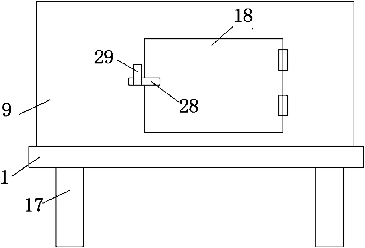
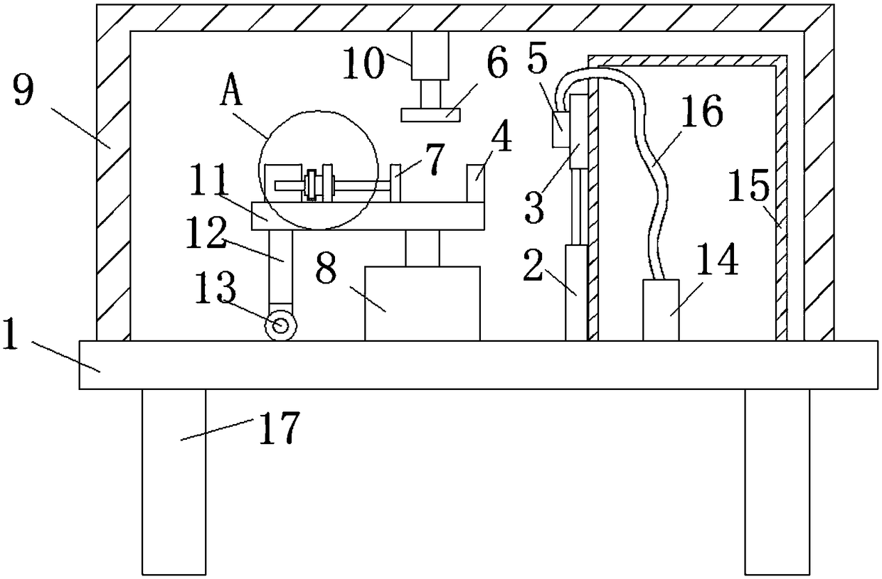
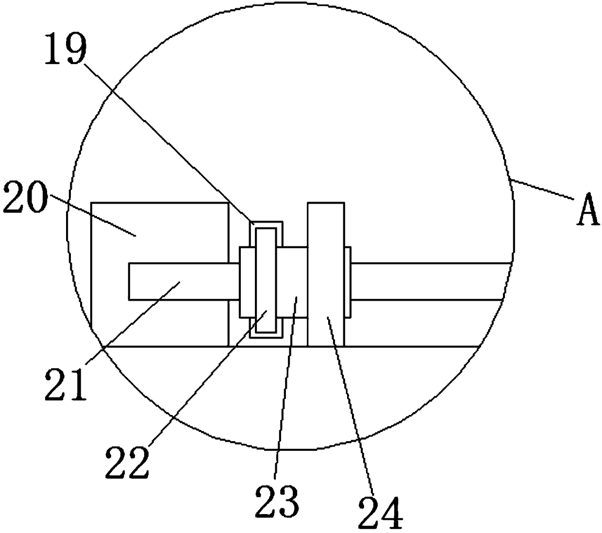

Image

  • Continuous coating device
  • Continuous coating device
  • Continuous coating device

Examples


Embodiment Construction

[0020] The following will clearly and completely describe the technical solutions in the embodiments of the present invention with reference to the accompanying drawings in the embodiments of the present invention. Obviously, the described embodiments are only some, not all, embodiments of the present invention.

[0021] In describing the present invention, it should be understood that the terms "upper", "lower", "front", "rear", "left", "right", "top", "bottom", "inner", " The orientation or positional relationship indicated by "outside", etc. is based on the orientation or positional relationship shown in the drawings, and is only for the convenience of describing the present invention and simplifying the description, rather than indicating or implying that the referred device or element must have a specific orientation, so as to Specific orientation configurations and operations, therefore, are not to be construed as limitations on the invention.

[0022] refer to Figure ...


PUM


Abstract

The invention discloses a continuous coating device. The continuous coating device comprises a bottom plate; a protective cover is fixedly connected with the upper surface of the bottom plate and is internally provided with a first rotating motor; the bottom end of the first rotating motor is fixedly connected with the upper surface of the bottom plate; the output end of the first rotating motor is fixedly connected with a supporting plate; the lower surface of the supporting plate is fixedly connected with a supporting rod; the bottom end of the supporting rod is fixedly connected with a universal wheel; a workpiece fixing mechanism is fixedly arranged on the upper surface of the supporting plate; an electric pushing rod and a material storing box are perpendicularly and fixedly connectedwith the upper surface of the bottom plate; the left side face of the material storing box is provided with a groove which is connected with a third fixing block in a sliding manner; and the left side face of the third fixing block is fixedly connected with a spraying head. The continuous coating device is easy to operate, saves time and labor, is convenient, fast and efficient, improves the workpiece fixing efficiency, can achieve continuous coating of workpieces, improves the coating quality, improves the workpiece coating efficiency and lowers the work intensity for coating personnel.

Description

technical field [0001] The invention relates to the technical field of coating equipment, in particular to a continuous coating device. Background technique [0002] Coating refers to covering the surface of an object with a layer of material, such as the common spray paint in factory production. Most of the existing coating devices use strip coating when coating the workpiece, and the nozzle needs to be moved after each coating is completed. Go to the original place to spray again. This kind of coating method is cumbersome to operate, time-consuming and labor-intensive, which reduces the efficiency of workpiece coating and increases the work intensity of operators. Moreover, the determination of the coating position is not very accurate each time, which will affect the coating quality. In addition, the existing coating device is very inconvenient to fix the workpiece, and the process is too cumbersome. Contents of the invention [0003] The purpose of the present inventi...

Claims


Application Information

Patent Timeline
IPC IPC(8): B05B16/00B05B9/04B05B13/02B05B13/04
CPCB05B9/0403B05B13/0228B05B13/0442B05B16/00
Inventor 张耀忠
Owner 张耀忠
Why Eureka
Try Eureka