Cathode bending separation device

A separation device and cathode technology, applied in the electrolysis process, electrolysis components, etc., can solve the problems of additional operation steps for multiple components, residual metal plates, occupying a relatively large processing site, etc., to achieve a simple and reliable structure and improve work efficiency. High efficiency and high peeling efficiency

Pending Publication Date: 2018-08-14
SANMEN SANYOU TECH CO LTD
View PDF7 Cites 5 Cited by
  • Summary
  • Abstract
  • Description
  • Claims
  • Application Information

AI Technical Summary

Problems solved by technology

[0002] The stripping procedures commonly used in the market at present are usually completed by multiple individual parts operating in sequence. This kind of process requires multiple mechanical parts. Multiple parts lead to a process that requires a relatively large processing site, and The connection between multiple parts requires additional operation steps, which is not conducive to streamlining procedures in the production process, and the cost is relatively high; in addition, due to the strong adhesion of the plate-like attachment on the metal plate during the peeling process, it is not conducive to The peeling process will cause adverse results such as incomplete peeling or residue on the metal plate

Method used


Image

  • Cathode bending separation device
  • Cathode bending separation device
  • Cathode bending separation device

Examples


Embodiment 1

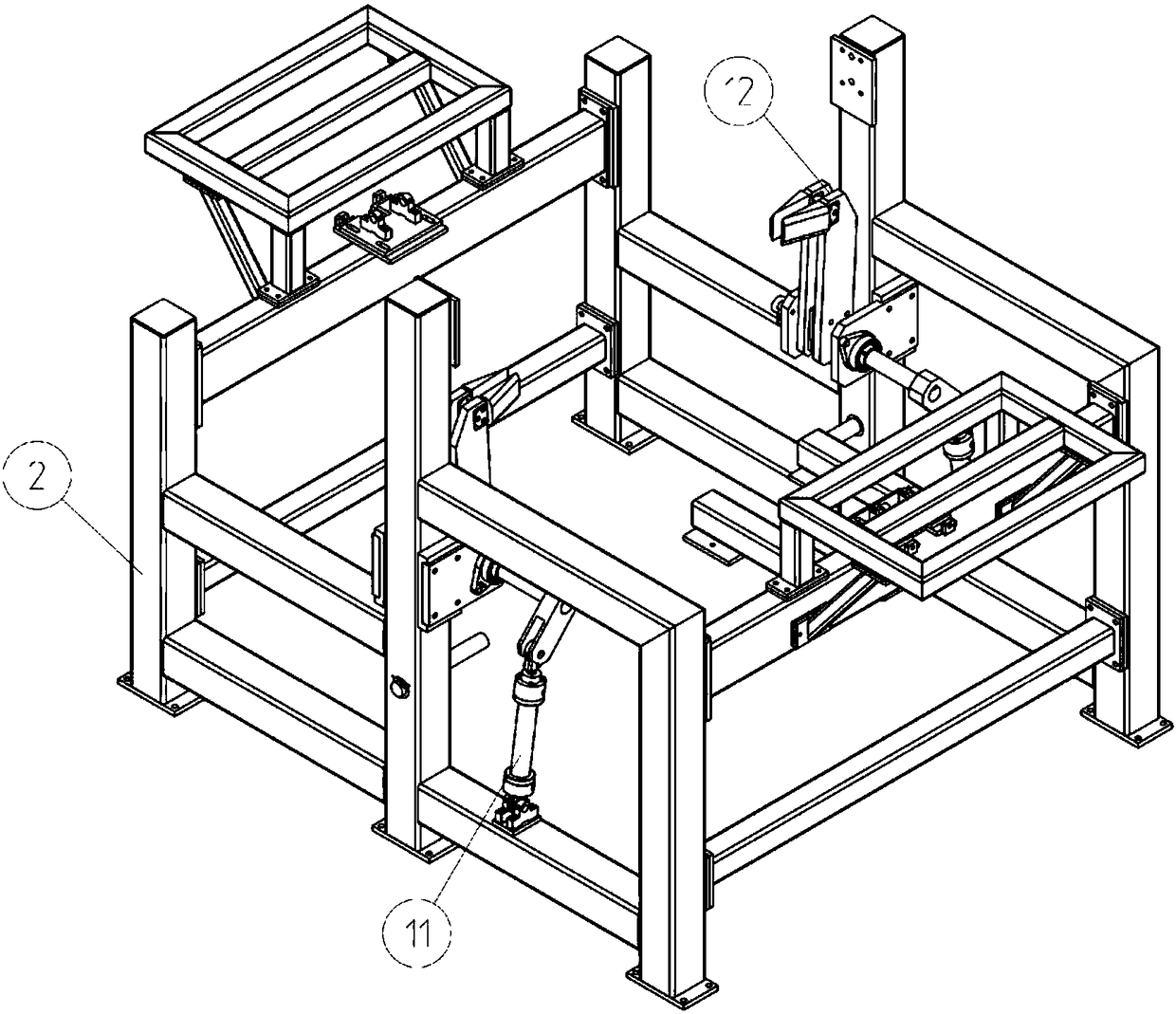
[0019] Embodiment 1: As shown in the accompanying drawings, this cathode deflection separation device mainly includes a cathode support assembly 1, a frame 2, a deflection strip assembly 3, a stripping knife assembly 4 and a driving device, and the frame 2 is provided with a stripping ax drive Oil cylinder 11, stripping ax 12, flex stripping assembly 3 is installed symmetrically on both sides of frame 2, stripping knife assembly 4 is installed on flex stripping assembly 3, cathode support assembly 1 is installed symmetrically on the middle top of frame 2. The driving device drives the opening and closing of the flexure stripping device, the rotation of the flexure body 15, and the rotation and advance and retreat of the stripping knife 18 to complete the flexure stripping operation. The frame 2 is used to install various mechanisms, and the stripping ax 12 is used to assist stripping.

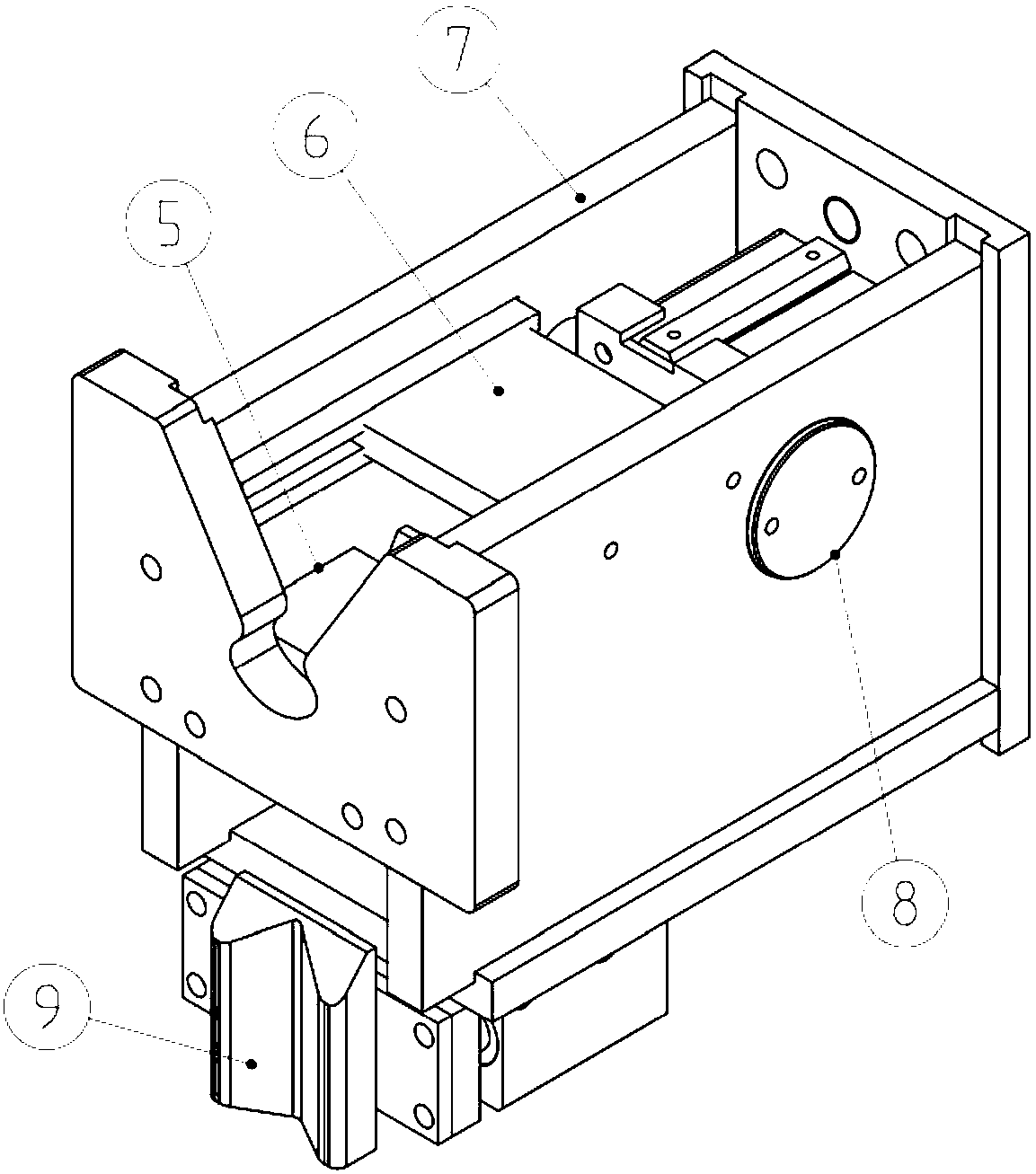
[0020] The cathode support assembly 1 is mainly composed of a limit mechanism 5, an anti-re...

Embodiment 2

[0024] Embodiment 2: When the robot puts the transferred cathode on the cathode support assembly 1, it will automatically center and adjust through the limit mechanism 5 during the descent process, and then use the side limit device 9 after the initial limit of the limit mechanism 5 Driven by the driving device, the cathode is precisely centered, and after centering, the anti-rebound mechanism 6 pushes the pressure plate out to cover both ends of the cathode under the drive of the driving device, preventing the cathode from popping out when it is peeled off.

[0025] When the cathode cannot be stripped normally, the stripping ax head 12 is driven by the stripping ax drive cylinder 11 to strip.

[0026] When the present invention is closed, the deflection lower limit ring 14 limits the bottom of the cathode, and at the same time, the flexure body 15 squeezes the cathode. Since the bottom of the cathode is limited, the cathode will generate an arc deformation to deflect the catho...


PUM


Abstract

The invention discloses a cathode bending separation device. The cathode bending separation device mainly comprises cathode support modules, a frame, bending stripping modules, stripping cutter modules and a driving device; the frame is provided with a stripping kettle driving oil cylinder and a stripping axe; the bending stripping modules are symmetrically mounted on the two sides of the frame, and are provided with the stripping cutter modules; and the cathode support modules are symmetrically mounted at the top in middle of the frame. The driving device drives opening and closing of the bending stripping modules, rotation of bending bodies and rotation, advancement and retreating of stripping cutters to finish the bending stripping operation. After the cathode bending separation deviceperforms the bending loosening on cathodes conveyed by a robot, the cathodes are separated by stripping knives or the stripping axe to finish the whole stripping process so as to facilitate realize automatic progress of a copper stripping unit; and the cathode bending separation device is simple and reliable in structure and high in stripping efficiency, protects the surfaces of cathode plates from being damaged, reduces the production scene noise, and achieves environmental protection.

Description

technical field [0001] The invention relates to the field of hydrometallurgical tools, in particular to a cathode deflection separation device. Background technique [0002] The stripping procedures commonly used in the market at present are usually completed by multiple individual parts operating in sequence. This kind of process requires multiple mechanical parts. Multiple parts lead to a process that requires a relatively large processing site, and The connection between multiple parts requires additional operation steps, which is not conducive to streamlining procedures in the production process, and the cost is relatively high; in addition, due to the strong adhesion of the plate-like attachment on the metal plate during the peeling process, it is not conducive to The peeling process will cause adverse results such as incomplete peeling or residue on the metal plate. Contents of the invention [0003] The purpose of the present invention is to overcome the shortcomin...

Claims


Application Information

Patent Timeline
IPC IPC(8): C25C7/08
CPCC25C7/08
Inventor 吴用吴俊义杨攀周成武李至青
Owner SANMEN SANYOU TECH CO LTD
Why Eureka
Try Eureka