
Door-window closing device and door-window both having automatic locking function

An automatic lock and closer technology, which is applied to the fastening devices of wing leaves, building fastening devices, buildings, etc., can solve the problems of not having automatic locking, inconvenient use and operation, and doors and windows being opened, so as to prevent Forget to lock the doors and windows, low production cost, easy installation

Pending Publication Date: 2018-08-10
HUNAN GOLDWELL NEW MATERIALS TECH CO LTD
View PDF0 Cites 4 Cited by
  • Summary
  • Abstract
  • Description
  • Claims
  • Application Information

AI Technical Summary

Problems solved by technology

The automatic closing of window and door leaves requires door and window closers, fire-proof temperature-controlled support rods, or temperature-sensitive closers to meet the closing conditions. Currently, door and window closers, fire-resistant temperature-controlled support rods, and temperature-sensitive closers on the market are expensive and difficult to install. complex, poor appearance
[0003] In addition, the door and window closers currently on the market do not have the function of automatic locking. After closing the doors and windows, the doors and windows need to be locked manually to lock the doors and windows, which is very inconvenient to use. Sometimes users forget to lock the doors and windows, and children or Pets can also easily push the doors and windows from indoors, which poses a certain security risk. In addition, if you forget to lock the doors and windows, the doors and windows can be opened from the outside, and the indoors will face the risk of theft

Method used


Image

  • Door-window closing device and door-window both having automatic locking function
  • Door-window closing device and door-window both having automatic locking function
  • Door-window closing device and door-window both having automatic locking function

Examples


Embodiment 1

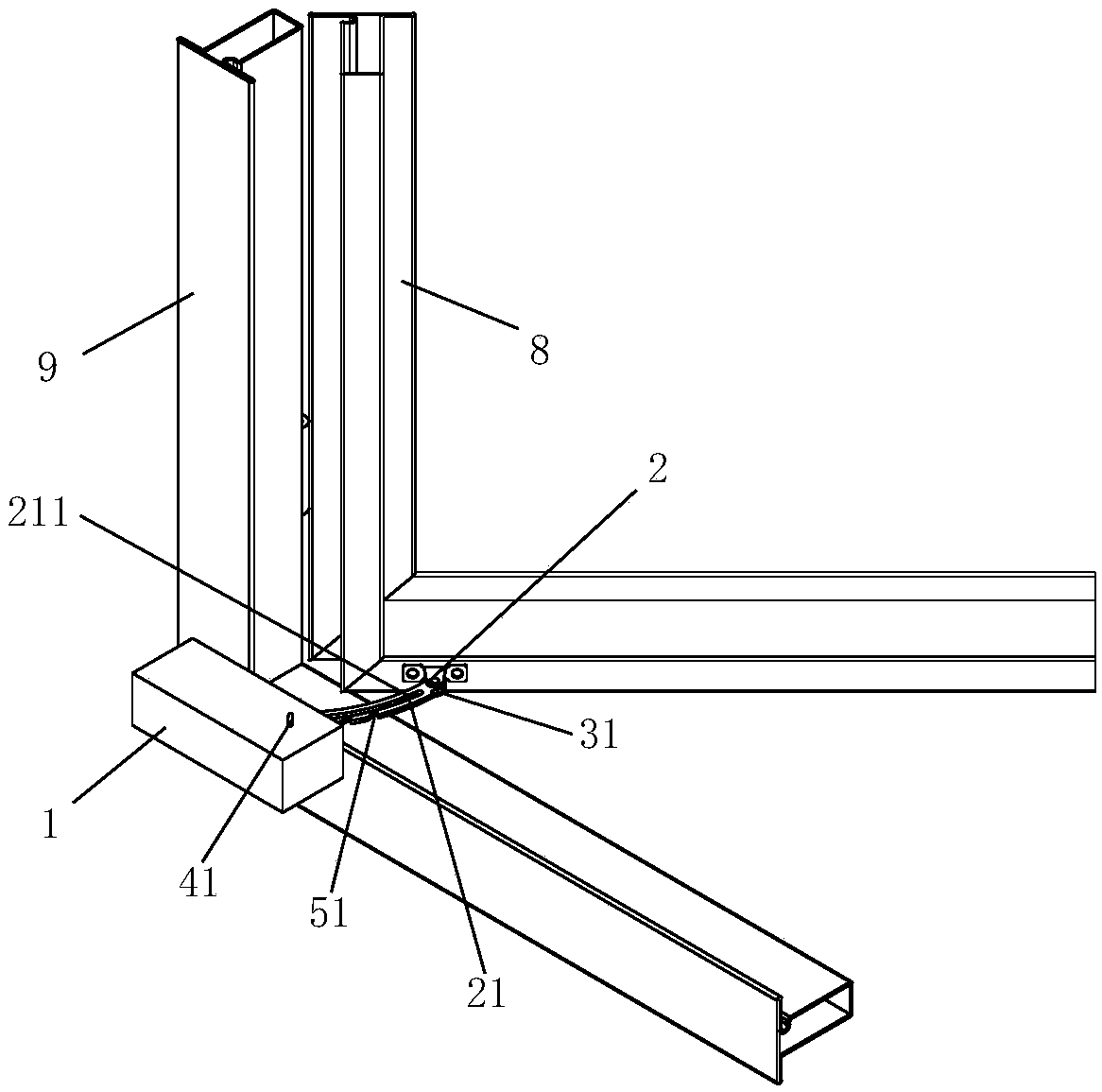
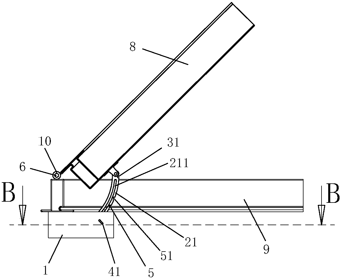
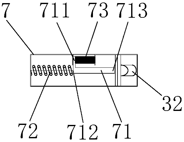
[0046] like Figure 1 to Figure 7 As shown, the automatic locking door and window closer of this embodiment includes a frame body connector 1 for connecting with the frame body 9 and a fan body connector 2 for connecting with the fan body 8, and the fan body connector 2 includes Arc-shaped support rod 21, one end of the support rod 21 is connected to the fan body 8 through the mounting seat, the support rod 21 is provided with an arc-shaped support rod guide groove 211, and the frame connector 1 is fixed to the frame body 9 The installation box on the top, the guide rod 12 for guiding the movement of the support rod guide groove 211 is fixedly installed in the installation box, the guide rod 12 is arranged in the support rod guide groove 211, and the door and window closer also includes automatic locking parts 3, The unlocking part 4 used to release the restriction of the automatic locking part 3 and the self-closing driving part 6 used to drive the fan body 8 to close, the au...

Embodiment 2

[0054] like Figure 8 to Figure 10 As shown, the automatic locking door and window closer of this embodiment includes a frame connector 1 for connecting with the frame 9 and a fan connector 2 for connecting with the fan 8, and the frame connector 1 includes The arc-shaped guide rail 13, the fan body connector 2 includes an arc-shaped support rod 21, one end of the support rod 21 is connected with the fan body 8 through the mounting seat, the other end of the support rod 21 is arranged on the guide rail 13, and the support rod 21 Can move along the guide rail 13, the center of circle of the guide rail 13 and the support rod 21 coincides with the position of the door and window rotating shaft 10, the door and window closer also includes an automatic locking part 3, an unlocking part 4 for releasing the restriction of the automatic locking part 3 and The self-closing driver 6 used to drive the sector 8 to close, the automatic locking member 3 includes a closed card slot 31 arrang...

Embodiment 3

[0062] like Figure 11 to Figure 15 As shown, the automatic locking door and window closer of this embodiment includes a frame connector 1 for connecting with the frame 9 and a fan connector 2 for connecting with the fan 8, and the fan connector 2 is The installation box affixed to the frame body 9 is provided with a guide groove 11, and the frame body connector 1 includes a support rod 21, and one end of the support rod 21 is arranged in the guide groove 11 and can slide along the guide groove 11 to support The other end of the rod 21 is arranged on the mounting seat connected with the frame body 9, the support rod 21 is pivotally connected with the mounting seat and can rotate around the pivot, and the door and window closer also includes an automatic locking member 3 for releasing the automatic locking member. 3 and the self-closing driver 6 for driving the fan body 8 to close. The automatic locking member 3 includes a closed card slot 31 arranged at the end of the support ...


PUM


Abstract

The invention discloses a door-window closing device and a door-window both having an automatic locking function. The door-window closing device comprises a frame body connecting piece for being connected with a frame body and a sash body connecting piece for being connected with a sash body; the frame body connecting piece and the sash body connecting piece are movably connected; the included angle between the frame body connecting piece and the sash body connecting piece can be adjusted and changed; the door-window closing device further comprises an automatic locking piece and an unlockingpiece, wherein the automatic locking piece is used for automatically locking and limiting relative movement between the frame body connecting piece and the sash body connecting piece when the sash body is closed, and the unlocking piece is used for relieving the limiting effect of the automatic locking piece; the automatic locking piece is arranged on the frame body connecting piece or the sash body connecting piece; and the unlocking piece is connected with the automatic locking piece. The door-window closing device is used on the door-window. The door-window closing device and the door-window are simple in structure, low in cost, convenient to mount and attractive in appearance, and meanwhile have the function of automatic locking.

Description

technical field [0001] The invention belongs to the technical field of building doors and windows, in particular to an automatic locking door and window closer and doors and windows. Background technique [0002] Existing fire doors and windows are equipped with door and window closers, and these door and window closers need to automatically close the window or door within 1 minute when the temperature rises to 74°C ± 0.5°C after a fire. The automatic closing of window and door leaves requires door and window closers, fire-proof temperature-controlled support rods, or temperature-sensitive closers to meet the closing conditions. Currently, door and window closers, fire-resistant temperature-controlled support rods, and temperature-sensitive closers on the market are expensive and difficult to install. Complicated and poor in appearance. [0003] In addition, the door and window closers currently on the market do not have the function of automatic locking. After closing the ...

Claims


Application Information

Patent Timeline
Patent Type & Authority Applications(China)
IPC IPC(8): E05C17/22E05C17/20
CPCE05C17/20E05C17/22
Inventor 李杰谢斌泉其他发明人请求不公开姓名
Owner HUNAN GOLDWELL NEW MATERIALS TECH CO LTD
Learn More