
A device for welding screw groups in the shipbuilding process

A manufacturing process and screw group technology, applied in welding equipment, manufacturing tools, auxiliary devices, etc., can solve the problems of low work efficiency and high work intensity of screw group, avoid route deviation, reduce work intensity, and improve work efficiency. Effect

Active Publication Date: 2019-10-08
WEIHAI VOCATIONAL COLLEGE
View PDF5 Cites 0 Cited by
  • Summary
  • Abstract
  • Description
  • Claims
  • Application Information

AI Technical Summary

Problems solved by technology

[0005] The purpose of the present invention is to provide a device for welding screw groups in the shipbuilding process, which is used to solve the problems of low work efficiency and high work intensity in the prior art for setting screw groups

Method used


Image

  • A device for welding screw groups in the shipbuilding process
  • A device for welding screw groups in the shipbuilding process
  • A device for welding screw groups in the shipbuilding process

Examples


Embodiment approach 1

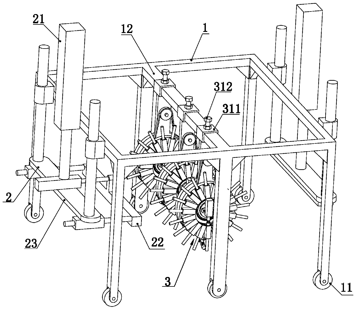
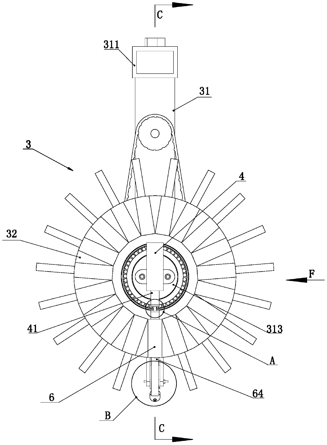
[0039] like figure 1 Shown, the present invention comprises driving frame 1, two groups of connecting frames 2 and some cloth welding machines 3, and driving frame 1 is provided with the wheel 11 that is used for convenient walking, and each connecting frame 2 is slidingly connected on driving frame 1 respectively. On, the connecting frame can slide on the driving frame 1 along the up and down direction. Each connecting frame is distributed along one front and one rear. Each connecting frame 2 and the driving frame 1 are respectively provided with lifting drivers 21 for driving the corresponding connecting frame 2 to slide up and down. Each connecting frame 2 is connected with an electromagnetic Iron 22.

[0040] like figure 1 As shown, the electromagnet 22 located on one and / or the other connecting frame 2 is slidably connected to the corresponding connecting frame 2 of the electromagnet 22, and the electromagnet 22 can slide in the front and rear direction on the correspon...

Embodiment approach 2

[0054] The difference between Embodiment 2 and Embodiment 1 lies in the arrangement of the welding head.

[0055] like Figure 12 and Figure 13 As shown, the bottom of the fixed disk is connected with a mounting frame 51, and the mounting frame 51 is slidably connected with a fixed ring 57. The fixed ring 57 can slide up and down on the mounting frame 51. A fixed ring driver 58 that drives the fixed ring 57 to slide vertically. The fixed ring 57 is provided with a moving ring 59, and the moving ring 59 is connected to the fixed ring 57 in rotation. The axis of the fixed ring 57 is arranged along the up and down direction. ring drive 591 . The moving ring 59 is connected with a welding rod 54, and the welding rod 54 is provided with a welding wire hole for passing the welding wire. The welding rod 54 is provided with a conveying wheel set for extruding and conveying the welding wire at one end of the welding wire hole. For example, the conveying wheel set includes two conv...


PUM


Abstract

The invention discloses a device for welding screw rod sets in a ship manufacturing process, relates to the technical field of welding machinery, and solves the problems of low working efficiency andhigh working intensity during setting of screw rod sets in the prior art. The device for welding the screw rod sets in the ship manufacturing process comprises a crane frame, two sets of connecting frames and multiple welding machines; the crane frame is provided with wheels facilitating walk; each connecting frame is slidingly connected to the crane frame; the connecting frames can slide on the crane frame in the up-down direction; the connecting frames are distributed front and back; lifting drivers for driving the corresponding connecting frames to slide up and down are arranged between theconnecting frames and the crane frame; the connecting frames are connected with electromagnets; and welding heads are used for welding screw rods on workpieces. The device has the beneficial effect of capability of improving the welding efficiency of the screw rod sets.

Description

technical field [0001] The invention relates to the technical field of welding machinery, in particular to a device for welding screw groups in the shipbuilding process. Background technique [0002] The detachable connection between large connecting parts usually requires a screw group to realize, especially in the shipbuilding industry, using a screw group to realize the connection between large parts is a technical method with high frequency of use. Each screw in a commonly used screw group is usually divided into rectangular arrays. When using screw sets, one end of each screw is usually welded to one of the connectors first. [0003] In the prior art, when the screw group is arranged on the connector, the construction personnel need to hold each screw separately and then weld the screws to the designated positions one by one, and each time a screw is welded, the screw needs to be positioned once. During the welding process, the staff needs to hold the screw for positi...

Claims


Application Information

Patent Timeline
Patent Type & Authority Patents(China)
IPC IPC(8): B23K37/00B23K37/04B23K37/02
Inventor 马红荣
Owner WEIHAI VOCATIONAL COLLEGE
Learn More