Force feedback master manipulator of minimally invasive surgical robot having redundant freedom degree
A technology of minimally invasive surgery and main manipulator, which is applied in the field of robot force feedback main manipulator and minimally invasive surgical robot force feedback main manipulator, which can solve the problem of expensive force feedback main manipulator, limited attitude angle output range, main The lack of freedom of the operator and other problems achieves the effect of compact structure, reduced quality and small space occupation
- Summary
- Abstract
- Description
- Claims
- Application Information
AI Technical Summary
Benefits of technology
Problems solved by technology
Method used
Image
Examples
specific Embodiment approach 1
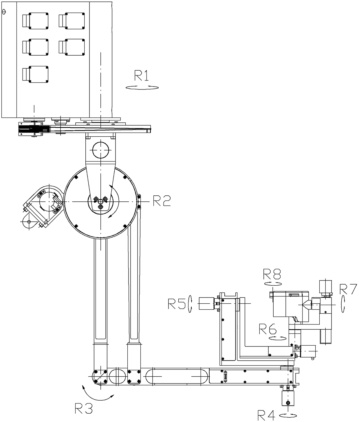
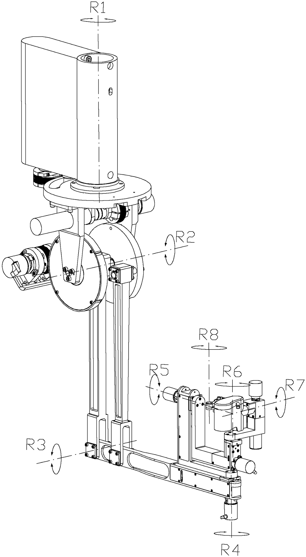
[0033] Specific implementation mode one: combine figure 1 and figure 2 Describe this embodiment, a minimally invasive surgical robot force feedback main operator with redundant degrees of freedom described in this embodiment, it includes a first drive joint 1, a second drive joint 2, a third drive joint 3, a fourth drive joint The drive joint 4, the fifth drive joint 5, the sixth drive joint 6, the seventh drive joint 7 and the eighth drive joint 8, the drive output end of the first drive joint 1 is connected with the drive input end of the second drive joint 2 and the drive input end of the second drive joint 2 respectively. The driving ends of the three driving joints 3 are connected, the second driving joint 2 is connected to the third driving joint 3, the driving output end connected to the third driving joint 3 is connected to the fourth driving joint 4, and the driving output end of the fourth driving joint 4 is connected to The fifth driving joint 5 is connected, the ...
specific Embodiment approach 2
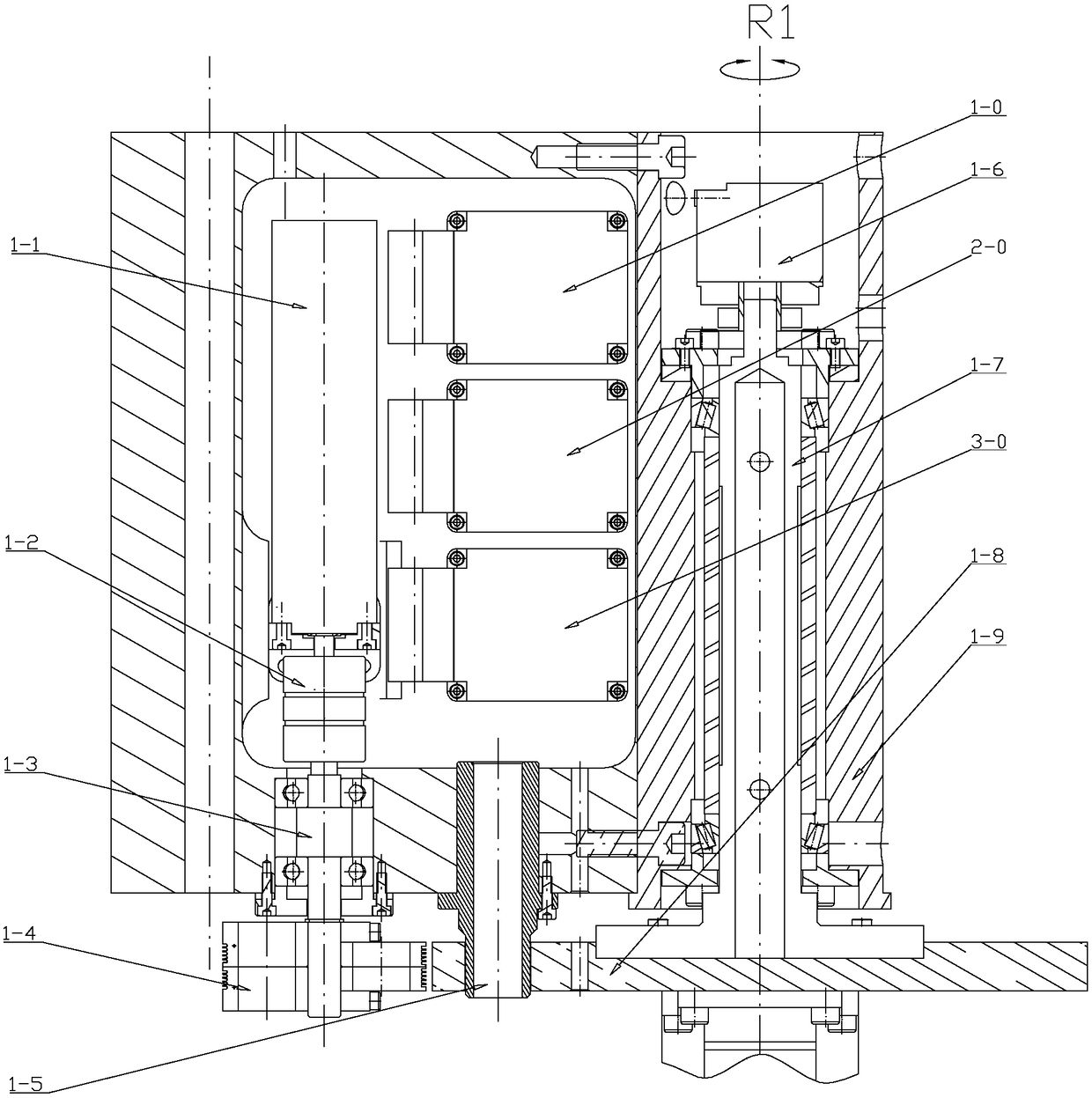
[0035] Specific implementation mode two: combination Figure 1-Figure 3 Describe this embodiment, a minimally invasive surgical robot force feedback main operator with redundant degrees of freedom described in this embodiment, the first drive joint 1 includes a first driver 1-0, a first drive motor 1-1, a first A shaft coupling 1-2, the first wire drum shaft 1-3, the first wire drum 1-4, the first limit pin 1-5, the first absolute angle encoder 1-6, the first rotating shaft 1- 7. The first drive joint output turntable 1-8 and the first drive joint base 1-9; the first drive 1-0, the first drive motor 1-1, the first coupling 1-2 and the first wire drum The shafts 1-3 are all installed on the first driving joint base 1-9, the first driver 1-0 is connected with the first driving motor 1-1, and one end of the first coupling 1-2 is connected with the first driving motor 1 -1 The output end of the rotating shaft is fixedly connected, the other end of the first coupling 1-2 is fixedl...
specific Embodiment approach 3
[0038] Specific implementation mode three: combination figure 1 , figure 2 , Figure 4-Figure 7 Describe this embodiment, a minimally invasive surgical robot force feedback main operator with redundant degrees of freedom described in this embodiment, the second drive joint 2 includes a second driver 2-0, a second drive motor 2-1, a second Two couplings 2-2, the second wire drum 2-3, the second wire drum shaft, the second absolute angle encoder 2-4, the second driving joint turntable 2-5, the second driving joint connecting rod 2- 6. The second drive joint shaft 2-7 and the second drive joint support 2-8; the third drive joint 3 includes a third driver 3-0, a third drive motor 3-1, a third coupling 3-2, The third wire drum 3-3, the third wire drum shaft, the third absolute angle encoder 3-4, the third driving joint turntable 3-5, the third driving joint connecting rod 3-6 and the third driving joint output rod 3-7; both the second driver 2-0 and the third driver 3-0 are ins...
PUM
 Abstract
Description
Claims
Application Information
 - R&D
- Intellectual Property
- Life Sciences
- Materials
- Tech Scout
- Unparalleled Data Quality
- Higher Quality Content
- 60% Fewer Hallucinations
Browse by: Latest US Patents, China's latest patents, Technical Efficacy Thesaurus, Application Domain, Technology Topic, Popular Technical Reports.
© 2025 PatSnap. All rights reserved.Legal|Privacy policy|Modern Slavery Act Transparency Statement|Sitemap|About US| Contact US: help@patsnap.com


