Auxiliary switch device for cut-off valve and cut-off valve

An auxiliary switch and cut-off valve technology, applied in the field of valve structure, can solve the problem of damage to the stop valve, achieve the effect of stable switch torsion operation and reduce adverse effects

Active Publication Date: 2020-11-17
QINGDAO HAIER AIR CONDITIONING ELECTRONICS CO LTD +1
View PDF4 Cites 0 Cited by
  • Summary
  • Abstract
  • Description
  • Claims
  • Application Information

AI Technical Summary

Problems solved by technology

[0004] The invention provides an auxiliary switch device for a cut-off valve and a cut-off valve, aiming to solve the problem that the switch operation mode of the existing cut-off valve easily causes damage to the cut-off valve

Method used


Image

  • Auxiliary switch device for cut-off valve and cut-off valve
  • Auxiliary switch device for cut-off valve and cut-off valve

Examples


Embodiment Construction

[0028] The following description and drawings fully illustrate specific embodiments of the present invention to enable those skilled in the art to practice them. Other implementations may include structural, logical, electrical, process, and other changes. The examples only represent possible changes. Unless explicitly required, individual components and functions are optional, and the order of operations can be changed. Parts and features of some embodiments may be included in or substituted for parts and features of other embodiments. The scope of the embodiments of the present invention includes the entire scope of the claims, and all available equivalents of the claims. In this document, each embodiment may be individually or collectively denoted by the term "invention", which is only for convenience, and if more than one invention is actually disclosed, it is not intended to automatically limit the scope of the application to any A single invention or inventive concept....


PUM


Abstract

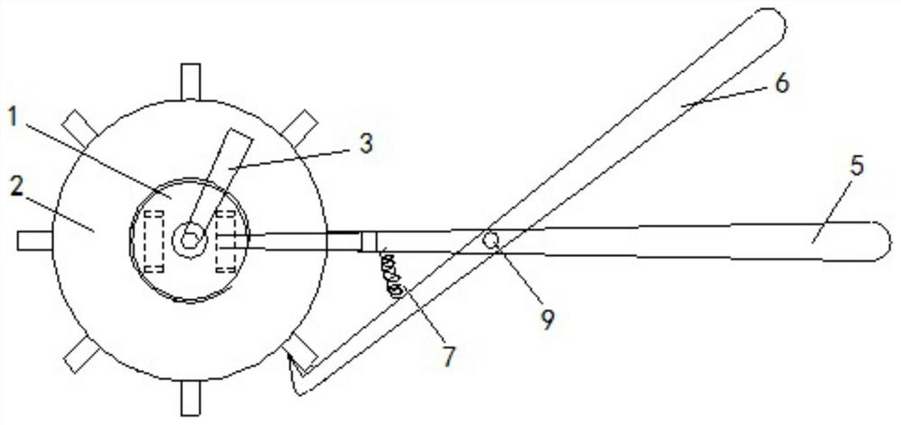
The invention discloses an auxiliary switch device for a stop valve, and belongs to the technical field of valve structures. The auxiliary switch device comprises a fixed disc, a movable disc, a torsion part and a clamping handle, wherein the fixed disc is used for being fixed to a valve body of the stop valve in a sleeving mode, the movable disc is arranged on the periphery of the fixed disc in asleeving manner and can rotate relative to the axial direction of the fixed disc, a plurality of clamping units are sequentially arranged on the periphery of the movable disc, one end of the torsionpart is used for being fixed to a rotary core of the stop valve, the other end of the torsion part is fixed to the movable disc, the clamping handle comprises a first clamping rod and a second clamping rod which form clamp-shaped pivot joint fit, the first end of the first clamping rod is connected to the fixed disc, the second end of the first clamping rod is a first handle end, the first end ofthe second clamping rod is provided with a clamping hook capable of being connected to any clamping unit in a hooked mode, and the second end of the second clamping rod is a second handle end. According to the auxiliary switch device for the stop valve, the torsion acting force of the valve body and the internal rotary core of the stop valve is converted into the acting force between the two clamping rods of the clamping handle, and the switch torsion operation of the stop valve can be more stable through the auxiliary switch device.

Description

Technical field [0001] The present invention relates to the technical field of valve structures, in particular to a shut-off valve auxiliary switching device and a shut-off valve. Background technique [0002] At present, the refrigerant pipeline of the air conditioner mostly uses a stop valve to control its on and off. Among them, the right angle valve is the most common. The front and back pipes of the right angle valve are 90 degrees. Due to the small size of the valve body, the general length is about 5 cm. , The height is about 4cm, the connected front and rear pipes will be subjected to shearing force when the core is twisted to control the switch, especially in the initial stage of opening will be subjected to greater shearing impact. [0003] Generally, the operation of twisting the shut-off valve is to fix the valve body with a wrench, and then use an inner hexagon to rotate the rotor of the shut-off valve. This type of operation sometimes causes problems that it is diffi...

Claims


Application Information

Patent Timeline
Patent Type & Authority Patents(China)
IPC IPC(8): F16K31/60F16K31/44
CPCF16K31/44F16K31/602
Inventor 冯维庆杨春雪李旭张晓迪夏鹏徐梦飞刘晓凯闫学勇
Owner QINGDAO HAIER AIR CONDITIONING ELECTRONICS CO LTD
Why Eureka
Try Eureka