
Foil bearing

A technology for bearings and bearing surfaces, applied to bearings, bearing components, shafts and bearings, etc., can solve the problem of high cost in manufacturing technology

Active Publication Date: 2018-08-03
SCHAEFFLER TECH AG & CO KG
View PDF6 Cites 5 Cited by
  • Summary
  • Abstract
  • Description
  • Claims
  • Application Information

AI Technical Summary

Problems solved by technology

The described retention of the membrane system in the bearing housing is on the one hand relatively expensive in terms of design and production technology
On the other hand, this bearing can only be used to a limited extent due to the one-sided fixing of the membrane system

Method used


Image

  • Foil bearing
  • Foil bearing
  • Foil bearing

Examples


Embodiment Construction

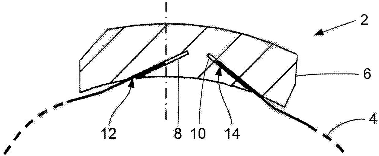
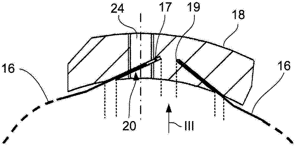
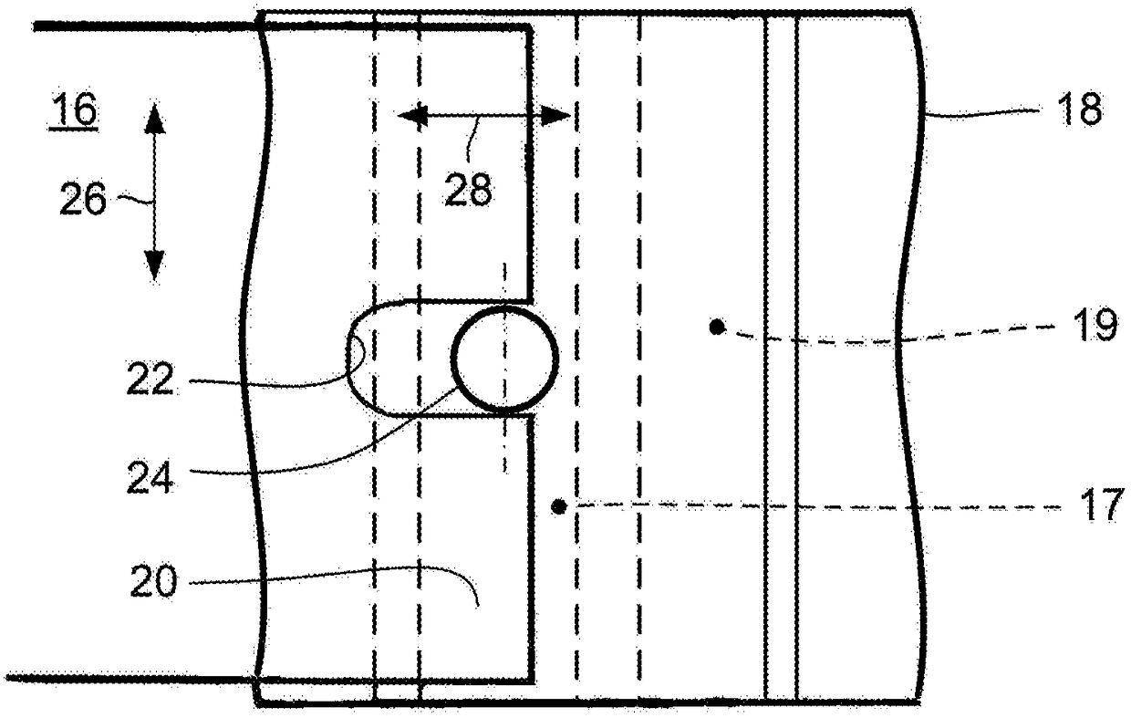
[0023] therefore, figure 1 A partial sectional view of the film bearing 2 is shown in the region of the fastening device for the cover film 4 , for example a single-sided bearing. On the inner side of the sleeve-shaped bearing housing 6 are formed plug-in grooves 8 , 10 oriented obliquely from the inside to the outside, end edges 12 , 14 bounding the cover film 4 in the circumferential direction and extending substantially in the circumferential direction. Fits into plug slot. The depth of the plug-in grooves 8 , 10 is greater than the insertion depth of the associated end edges 12 , 14 in the case of an unloaded cover film, wherein the plug-in grooves 8 , 10 each have a sliding fit. The associated end edges 12 , 14 are accommodated. When the cover film 4 is subjected to mechanical or thermal loads, the end edges 12 , 14 can be displaced into the associated plug-in grooves 8 , 10 so that the cover film 4 can be adapted to the load-induced stresses of the film system. deform...


PUM


Abstract

The invention relates to a foil bearing (30) for supporting a shaft (36), said bearing comprising a sleeve-type bearing housing (32), at least one elastic corrugated foil (34) arranged on the inner circumference of the bearing housing and a respective top foil (38) covering each corrugated foil and forming a bearing surface, means for securing said foils being provided on the inner face of the bearing housing (32). According to the invention, insertion grooves (40, 42) are formed in the inner face of the bearing housing (32), the insertion grooves extending along surface lines, running obliquely from the inside to the outside and being used to hold at least the two end edges (44, 46) which delimit the top foil (38) of each foil arrangement in the circumferential direction and which run substantially in the circumferential direction. Alternatively, end edges (48, 50) which likewise engage in the insertion grooves (40, 42) can be formed on the corrugated foils.

Description

technical field [0001] The invention relates to a membrane bearing for supporting a shaft, comprising a sleeve-shaped bearing housing, at least one elastic corrugated membrane arranged on the inner circumference of the bearing housing and a respective covering corrugated membrane Forming the covering film of the bearing surface, wherein means for fixing the mentioned film are arranged on the inner side of the bearing housing. Background technique [0002] Film bearings are hydrodynamic or aerodynamic bearings in which, in the unloaded condition of the bearing, the bearing surface supporting the shaft or supporting the rotor supported in rotation is formed by a thin, wear-resistant covering film, the covering film itself is supported by an elastic, corrugated membrane arranged between the covering membrane and the bearing housing wall. During operation, a hydrodynamic or aerodynamic thin layer carrying the shaft or the rotor is formed between the shaft and the covering film....

Claims


Application Information

Patent Timeline
Patent Type & Authority Applications(China)
IPC IPC(8): F16C17/02
CPCF16C17/024F16C27/02F16C43/02
Inventor 沃尔夫冈·布朗西蒙·魏纳菲利普·沃思
Owner SCHAEFFLER TECH AG & CO KG
Learn More