
Width-adjustable rail car walking mechanism

A technology of traveling mechanism and rail car, which is applied in the direction of wheels, wheels, and vehicle parts characterized by rail running parts, which can solve the problems of easy wear or jamming of rail cars, reduce wear, improve flexibility, and prevent jamming dead effect

Pending Publication Date: 2018-08-03
NORTH CHINA UNIV OF WATER RESOURCES & ELECTRIC POWER
View PDF0 Cites 4 Cited by
  • Summary
  • Abstract
  • Description
  • Claims
  • Application Information

AI Technical Summary

Problems solved by technology

[0003] The object of the present invention is to provide a rail car running mechanism with adjustable width to solve the problem in the prior art that the rail car is easy to wear or get stuck due to changes in the width of the track

Method used


Image

  • Width-adjustable rail car walking mechanism
  • Width-adjustable rail car walking mechanism
  • Width-adjustable rail car walking mechanism

Examples


Embodiment 1

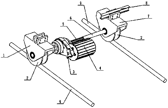
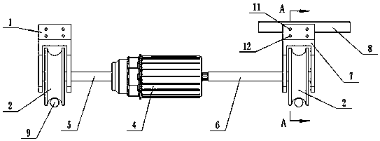
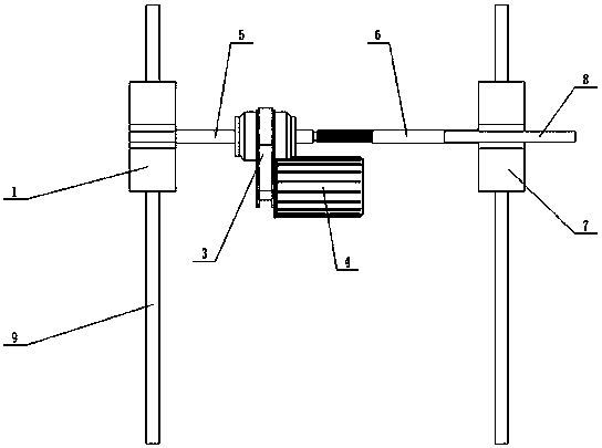
[0028] A rail car running mechanism with adjustable width, such as Figure 1-5 As shown, it includes a track running part and a width adjusting part arranged on the track running part. Wherein, the rail running part includes a driving device, a power shaft and a rail wheel 2, the rail wheel 2 travels on a set of rails 9, and the rail wheel 2 is connected to the power shaft through a bearing seat. In this example, the power shaft includes a spline shaft 5 and a sleeve shaft 6. The sleeve shaft 6 and the spline shaft 5 are connected by a sliding spline, and both can move left and right relatively, while the sleeve shaft 6 and the spline shaft 5 The circumferential direction is positioned by splines. The left end of the spline shaft 5 is provided with a left end track wheel, and the left end track wheel is rollingly connected with the spline shaft 5 through the fixed bearing seat 1. The right end of sleeve shaft 6 is provided with a right end track wheel, and the right end trac...

Embodiment 2

[0035] Such as Figure 6-9As shown, the difference from Embodiment 1 is that the installation positions of the roller shaft 12 and the deep groove ball bearing 10 on the roller shaft 12 are different. Specifically, in Embodiment 2, the deep groove ball bearing 10 is fixed in the through hole at the lower end of the vertical plate on the mobile bearing seat 7, the outer peripheral surface of the roller 12 is in rolling contact with the lower end surface of the lower plate of the connecting plate, and the roller 12 Roll fit with the lower plate of the connecting plate.

[0036] The width-adjustable rail car traveling mechanism of the present invention is suitable for occasions where the track installation accuracy is low such as farmland and orchards, so as to automatically adapt to changes in the width of the track.

[0037] Embodiment 3 of a width-adjustable railcar running mechanism is different from Embodiment 1 in that a sleeve shaft 6 is also provided at the left end of t...


PUM


Abstract

The invention discloses a width-adjustable rail car walking mechanism comprising a track walking component and a width adjustment component arranged on the track walking component. The track walking component includes a power shaft and track wheels disposed at the two ends of the power shaft. The power shaft includes a spline shaft and a sleeve shaft which can perform relative left-right movement.The track wheels are in rolling connection with the sleeve shaft through a moving bearing block, and the moving bearing block performs left-right movement relative to the width adjustment component.The track wheels and the moving bearing block perform left-right movement relative to the width adjustment component, so that the spline shaft and the sleeve shaft are driven to perform relative left-right movement, to adjust the length of the power shaft, to adapt to the track width change, reduce rail car abrasion and prevent the rail car from being blocked or even turned over.

Description

technical field [0001] The invention relates to agricultural machinery, in particular to a rail vehicle traveling mechanism with adjustable width. Background technique [0002] During the planting of crops, field mechanized operations such as weeding, spraying, fertilizing, and harvesting require operating vehicles to walk along the pre-laid tracks in the field. However, because the track installation in farmland and orchards is not as precise as industrial tracks, the two tracks are wide and narrow. , the width change even reaches 20 cm, and the change of the track width is easy to cause the rail car to wear out, even get stuck, roll over, etc. Therefore, the wheel base of the agricultural vehicle chassis is required to be adjusted as the track width changes. Therefore, a rail car running mechanism with adjustable width has come into being. Contents of the invention [0003] The object of the present invention is to provide a rail car running mechanism with adjustable w...

Claims


Application Information

Patent Timeline
Patent Type & Authority Applications(China)
IPC IPC(8): B60B17/00
CPCB60B17/00
Inventor 范素香何培雄徐海铭汤鹏飞朱思颖
Owner NORTH CHINA UNIV OF WATER RESOURCES & ELECTRIC POWER
Learn More