
Spanner and clamping-and-holding assembly thereof

A clamping piece and wrench technology, applied to wrenches, manufacturing tools, wrenches, etc., can solve the problem of low working efficiency of conventional wrenches, achieve large torsional resistance and improve work efficiency

Pending Publication Date: 2018-08-03
HENAN SENYUAN ELECTRIC CO LTD
View PDF11 Cites 0 Cited by
  • Summary
  • Abstract
  • Description
  • Claims
  • Application Information

AI Technical Summary

Problems solved by technology

[0003] The purpose of the present invention is to provide a wrench to solve the problem of low working efficiency of conventional wrenches, and the present invention is also to provide a clamping assembly

Method used


Image

  • Spanner and clamping-and-holding assembly thereof
  • Spanner and clamping-and-holding assembly thereof
  • Spanner and clamping-and-holding assembly thereof

Examples


specific Embodiment 2

[0023] In the second embodiment of the wrench of the present invention, the difference between this embodiment and the above-mentioned specific embodiment 1 of the wrench is only: the threaded fastener in this embodiment is a fastener bolt or other detachable threaded fastener, Connect the inserted clamping piece and the main rod through the long hole.

specific Embodiment 3

[0024] In the third embodiment of the wrench of the present invention, the difference between this embodiment and the above-mentioned specific embodiment 1 of the wrench is only that: the hole in this embodiment is a square hole, and the square hole is in the circumferential direction around the main rod The size is larger than the radial size of the mating part of the threaded fastener.

[0025] In the fourth embodiment of the wrench of the present invention, the difference between this embodiment and the above-mentioned specific embodiment 1 of the wrench is only that: the length of the elongated hole located on the retaining member in this embodiment is equal to six of the circumference of the retaining member. One part or other dimensions that are larger than one-twelfth of the circumference of the holder and smaller than one.

specific Embodiment 5

[0026] In the fifth embodiment of the wrench of the present invention, the difference between this embodiment and the first embodiment of the above wrench is only that: the length of the elongated hole at the end of the main rod in this embodiment is equal to the circumference of the end of the main rod One-sixth or less than one-sixth of the circumference of the main rod end.

[0027] In the sixth embodiment of the wrench of the present invention, the difference between this embodiment and the first embodiment of the above wrench is only that: the elongated hole in this embodiment is located on the clamping member, and the width of the elongated hole is fixed Double or 2.5 times the screw diameter or other size larger than the diameter of the set screw.

[0028] In the seventh embodiment of the wrench of the present invention, the difference between this embodiment and the above-mentioned specific embodiment 1 of the wrench is only that: the elongated hole in this embodiment is lo...


PUM


Abstract

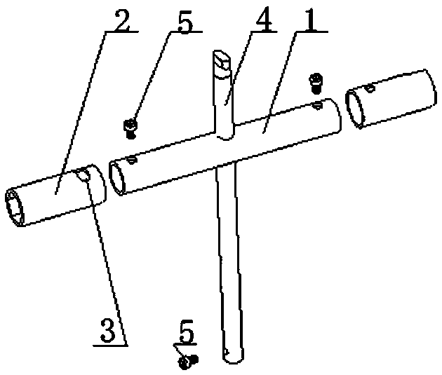
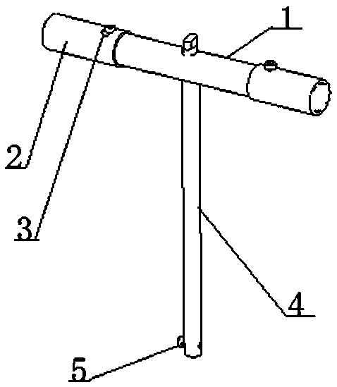
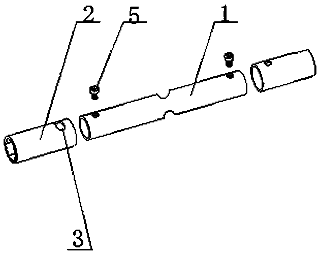
The invention belongs to the field of threaded fastener disassembly tools, and particularly relates to a spanner and a clamping-and-holding assembly thereof. The spanner includes a spanner handle andthe clamping-and-holding assembly, wherein the clamping-and-holding assembly includes clamping-and-holding members, a main rod and set screws. A through long hole is formed in the main rod, the spanner handle penetrates through the through long hole in the main rod and is connected with the main rod, two ends of the main rod are connected with the clamping-and-holding members, and each clamping-and-holding member is provided with a long hole, wherein the extending length of the long hole in the circumferential direction is equal to one twelfth of the circumference of the clamping-and-holding member, and the width of the long hole is equal to the diameter of the corresponding set screw. The set screws penetrate through the long holes to connect the inserted clamping-and-holding members andthe main rod so that when the spanner works and the clamping-and-holding members and fasteners are not fully matched, the clamping-and-holding members can be rotated to realize the cooperation of theclamping-and-holding members and the fasteners. When the spanner works in a special environment with small operable space, the rotation angle of the spanner can be ensured to the maximum, so that theworking efficiency can be improved in special environments.

Description

Technical field [0001] The invention belongs to the field of threaded fastener disassembly tools, and in particular relates to a wrench and a clamping component thereof. Background technique [0002] Wrenches are widely used in many fields that require disassembly and installation of threaded connections. There are many types of wrenches on the market, but most of the main rods and handles of wrenches are fixed connections, which takes up a lot of space during storage and carrying. In order to solve this problem, the Chinese invention patent with the authorized announcement number CN103753461A and the authorized announcement date of 2014.04.30 discloses a combination wrench. The combination wrench includes a main rod and a wrench handle. The wrench handle is movably connected to the main rod. , The end of the main rod is provided with a detachable sleeve. The sleeve and the main rod are detachably fixed by bolts. The sleeve and the main rod are fixed and assembled. During disasse...

Claims


Application Information

Patent Timeline
Patent Type & Authority Applications(China)
IPC IPC(8): B25B13/48B25B13/58
CPCB25B13/481B25B13/58
Inventor 张智磊赵小莹
Owner HENAN SENYUAN ELECTRIC CO LTD
Learn More