Tail line-out knob adjusting structure of draw-arc-type stud welding gun

A technology of adjusting structure and stud welding, applied in arc welding equipment, welding rod characteristics, welding equipment and other directions, can solve the problems of difficult clamping of the manipulator, easy scalding of the operator, and difficult clamping of the manipulator, so as to solve the problems of poor welding and welding. limitations, solve difficult operation problems, and adjust the effect of simple and convenient

Active Publication Date: 2018-08-03
安徽华生机电集团有限公司
View PDF6 Cites 0 Cited by
  • Summary
  • Abstract
  • Description
  • Claims
  • Application Information

AI Technical Summary

Problems solved by technology

[0004] In the above application, after the arc is struck, the main shaft body can be reset smoothly through the damper. The setting of the adaptive structure ensures the smooth axial sliding of the main shaft body. The setting of the locking structure can maintain the set lifting gap unchanged, but no indicator is set. , it is impossible to adjust accurately and effectively; in addition, due to the improvement of automation, and the electric spark generated by the stud welding torch at the moment of welding is easy to burn the operator, the manipulator is now used to hold the drawn arc stud welding torch for welding. The drawn-arc stud welding torch comes out from the bottom of the handle, so it is difficult to clamp the manipulator. For example, when the manipulator is required to work automatically, due to the influence of the handle and the power cord, the power cord is likely to interfere with the welding process when welding studs , the handle cannot be disassembled due to the outlet method, making it difficult for the manipulator to clamp, resulting in defects and low efficiency during automatic welding

Method used


Image

  • Tail line-out knob adjusting structure of draw-arc-type stud welding gun
  • Tail line-out knob adjusting structure of draw-arc-type stud welding gun
  • Tail line-out knob adjusting structure of draw-arc-type stud welding gun

Examples


Embodiment Construction

[0019] The following will clearly and completely describe the technical solutions in the embodiments of the present invention with reference to the accompanying drawings in the embodiments of the present invention. Obviously, the described embodiments are only some, not all, embodiments of the present invention. Based on the embodiments of the present invention, all other embodiments obtained by persons of ordinary skill in the art without making creative efforts belong to the protection scope of the present invention.

[0020] see Figure 1~4 , the present invention provides a technical solution:

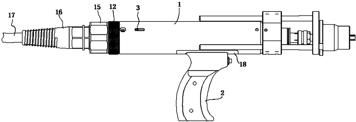
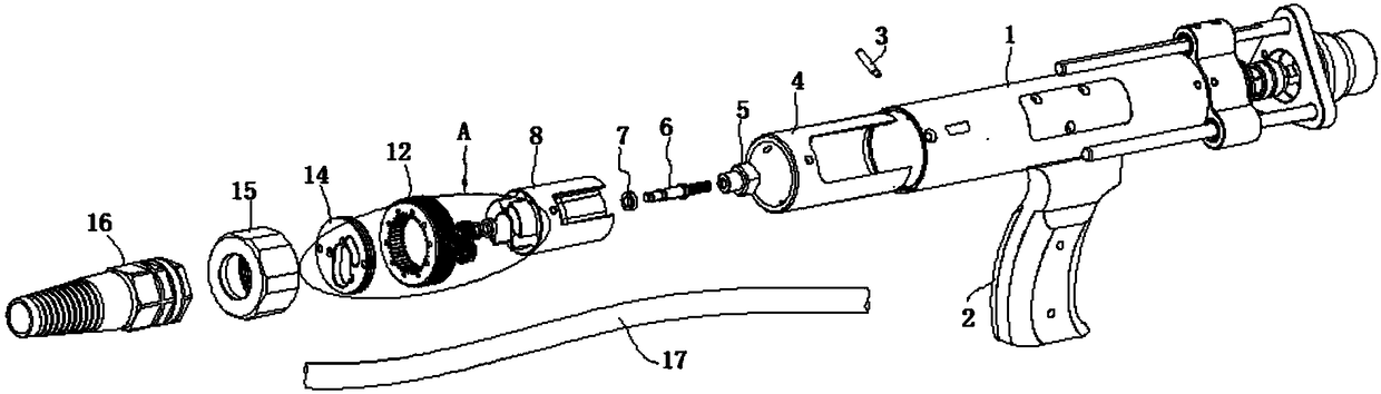
[0021] The drawn arc stud welding torch of the present invention includes a welding torch main body 1 , a tail outlet knob adjustment structure, a detachable handle and a power cord 17 .

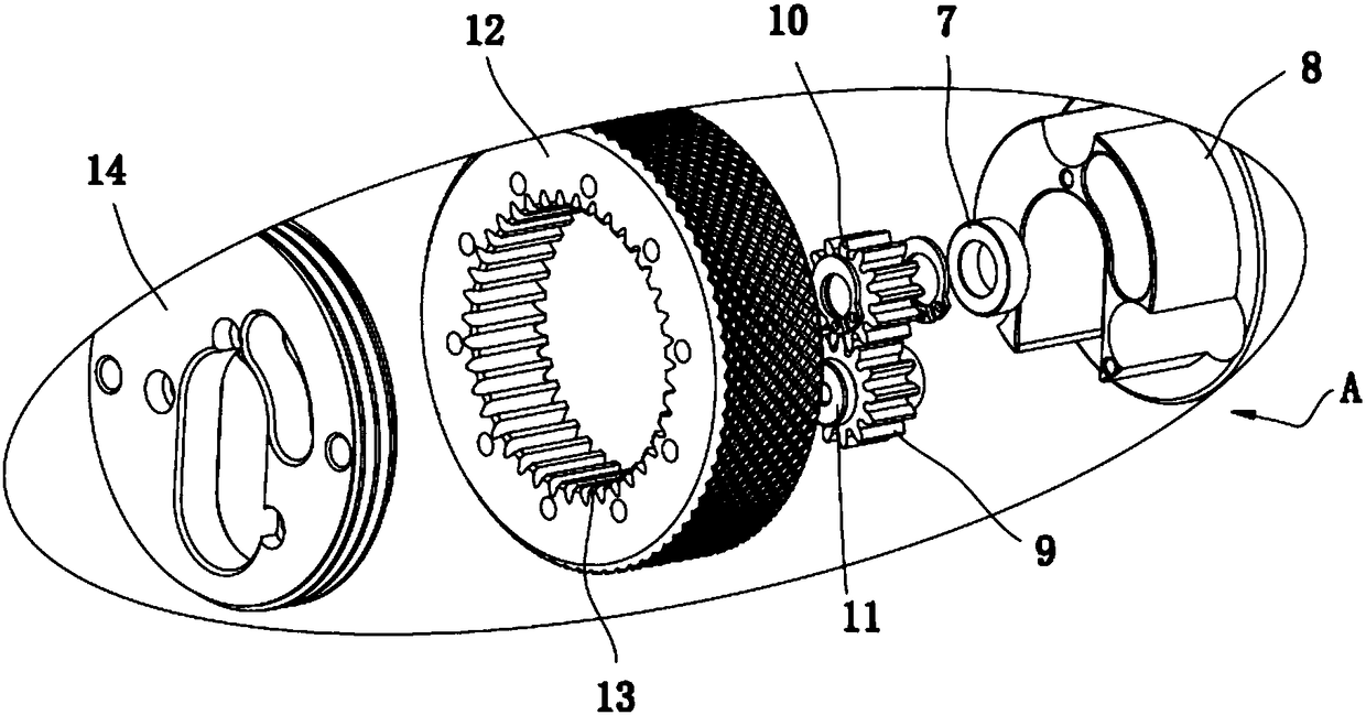
[0022] The tail outlet knob adjustment structure is arranged at the tail of the welding torch body 1, which includes an indicator column 3, a threading inner sleeve 4, a limit seat 5, an adjustm...


PUM


Abstract

The invention discloses a tail line-out knob adjusting structure of a draw-arc-type stud welding gun. The tail line-out knob adjusting structure is arranged at the tail part of a welding gun main body. A power line is arranged at the tail part of the welding gun main body through the tail line-out knob adjusting structure. An inner gear is arranged in a knob. A transmission gear assembly meshes with the inner gear and a driven gear simultaneously. The driven gear is fixed to an adjusting screw rod. One end of the adjusting screw rod is movably mounted in an adjusting seat through two first bearings. The other end of the adjusting screw rod is mounted in a limiting seat through threads. According to the tail line-out knob adjusting structure, transmission is conducted by adopting the innergear, the transmission gear assembly and the driven gear, so that the adjusting screw rod is driven to rotate, the limiting seat is driven to move back and forth in the axial direction of the adjusting screw rod, and the function of adjusting the draw-arc distance is achieved; and because the tail line-out knob adjusting structure is a gear transmission system, the interior of the welding gun mainbody can have a large space for storing the power line, and the mode that the line only can come out from the bottom of a handle in the prior art is eliminated.

Description

technical field [0001] The invention relates to the technical field of drawn-arc stud welding torches, in particular to an adjustment structure of a wire outlet knob at the tail of a drawn-arc stud welding torch. Background technique [0002] Drawn arc stud welding guns are widely used in automobile, shipbuilding, aviation, locomotive and other sheet metal industries. The stud welding gun uses the current output by the welding machine to form an arc between the welding sheet metal parts and the welding studs through the lifting of the electromagnet, so that the welding studs and the sheet metal parts melt at the same time, and then through the control of the controller, the electromagnet is turned off. Current, the conductive end part drives the welding nail to press into the molten pool of the sheet metal part under the pressure of the spring, and the welding is completed at one time. The whole welding process only takes tens of milliseconds. [0003] In the prior art, su...

Claims


Application Information

Patent Timeline
IPC IPC(8): B23K9/28B23K9/20
CPCB23K9/20B23K9/28
Inventor 许克生董磊
Owner 安徽华生机电集团有限公司
Why Eureka
Try Eureka