
Automatic welding system for corrugated membrane sheet of membrane type liquefied-gas cargo hold, structure for guiding and fixing automatic welding apparatus for corrugated membrane sheet of membrane type liquefied-gas cargo hold, and structure for guiding automatic welding apparatus for corrugated membrane sheet of membrane type liquefied-gas cargo hold

A technology of automatic welding and corrugated film, which is applied in the direction of bulk goods, fixed-capacity gas storage tanks, welding equipment, etc., can solve the problems of machinability and stability degradation, support automatic welding machinery, difficulties, etc.

Inactive Publication Date: 2018-07-31
DAEWOO SHIPBUILDING & MARINE ENG CO LTD
View PDF5 Cites 0 Cited by
  • Summary
  • Abstract
  • Description
  • Claims
  • Application Information

AI Technical Summary

Problems solved by technology

[0032] However, typical structures for fastening automatic welding machines are difficult to stably support automatic welding machines during automatic welding of corrugated diaphragms
Especially, during the welding of the upper surface and the side surface of the warehouse, it is more difficult to support the automatic welding machine with such a typical fastening structure due to the weight of the automatic welding machine, thereby deteriorating workability and stability

Method used


Image

  • Automatic welding system for corrugated membrane sheet of membrane type liquefied-gas cargo hold, structure for guiding and fixing automatic welding apparatus for corrugated membrane sheet of membrane type liquefied-gas cargo hold, and structure for guiding automatic welding apparatus for corrugated membrane sheet of membrane type liquefied-gas cargo hold
  • Automatic welding system for corrugated membrane sheet of membrane type liquefied-gas cargo hold, structure for guiding and fixing automatic welding apparatus for corrugated membrane sheet of membrane type liquefied-gas cargo hold, and structure for guiding automatic welding apparatus for corrugated membrane sheet of membrane type liquefied-gas cargo hold
  • Automatic welding system for corrugated membrane sheet of membrane type liquefied-gas cargo hold, structure for guiding and fixing automatic welding apparatus for corrugated membrane sheet of membrane type liquefied-gas cargo hold, and structure for guiding automatic welding apparatus for corrugated membrane sheet of membrane type liquefied-gas cargo hold

Examples


Embodiment Construction

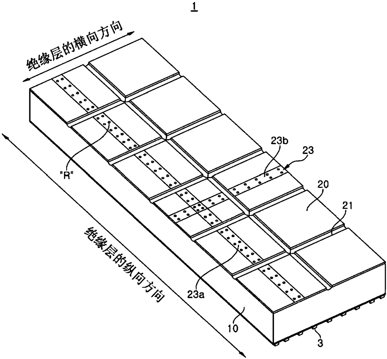
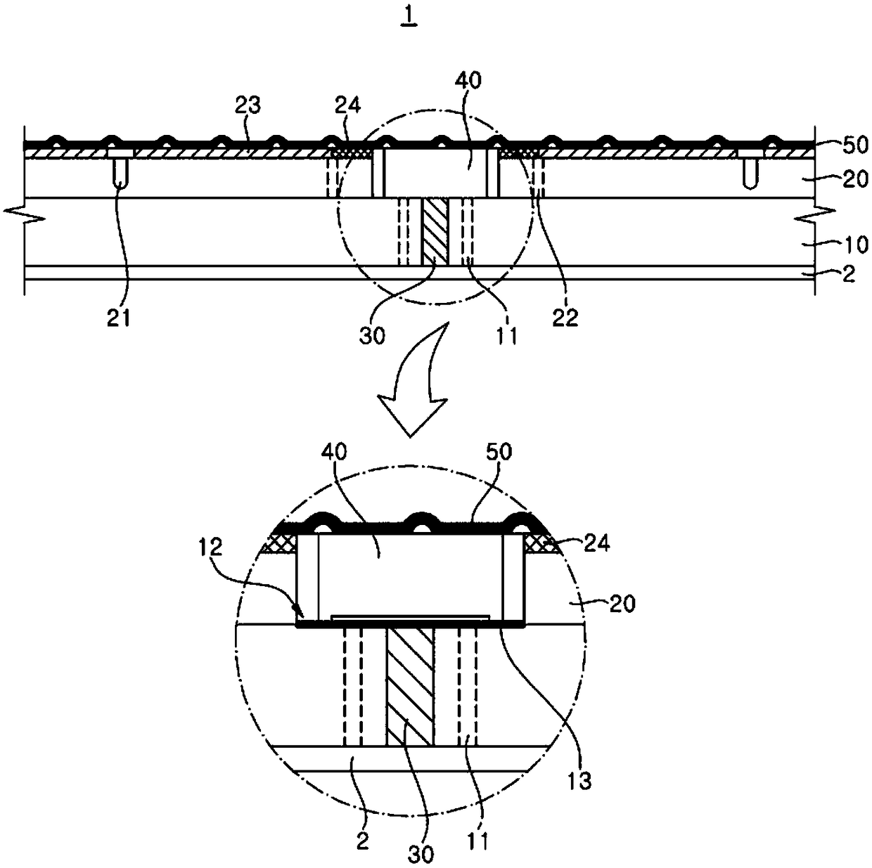
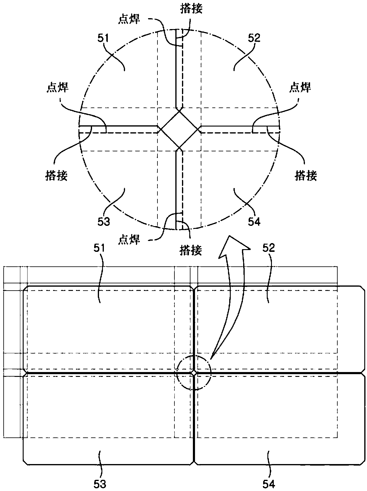
[0062] According to the present invention, a corrugated diaphragm automatic welding system for a membrane-type liquefied gas tank includes: a longitudinal anchoring strip arranged in the longitudinal direction of an insulating layer, the insulating layer including a corrugated diaphragm as a first barrier; a transverse anchor An anchoring strip arranged in the transverse direction of the insulating layer; a cross anchoring strip arranged at the junction between the longitudinal anchoring strips and the transverse anchoring strips, the crossing anchoring strips having a fastening a groove; a vertical support firmly set in the fastening groove; a welding guide connected to the vertical support; and an automatic welding device movable along the welding guide to pair the adjacent The corners of the corrugated diaphragm are lap welded.

[0063] The automatic welding device may include: a main body including a rail in which the welding guide is embedded; a moving wheel provided on t...


PUM

PropertyMeasurementUnit
thicknessaaaaaaaaaa

Abstract

The present invention relates to an automatic welding system for a corrugated membrane sheet of a membrane type liquefied-gas cargo hold, a structure for guiding and fixing an automatic welding apparatus for a corrugated membrane sheet of a membrane type liquefied-gas cargo hold, and a structure for guiding an automatic welding apparatus for a corrugated membrane sheet of a membrane type liquefied-gas cargo hold. When a corrugated membrane sheet is welded, a cross-anchor strip having a fixing groove is installed on a portion where longitudinal and lateral anchor strips, which are attached to the upper surface of a heat insulating panel on which the corrugated membrane sheet is mounted, cross each other, which makes it possible to install a welding guide that supports the automatic weldingapparatus and guides a movement of the automatic welding apparatus using the fixing groove, thereby stably performing automatic welding on the corrugated membrane sheet.

Description

technical field [0001] The present invention relates to a corrugated diaphragm automatic welding system for membrane-type liquefied gas cargo tanks, and more specifically to a corrugated diaphragm automatic welding system for membrane-type liquefied gas cargo tanks, a method for guiding and fastening membrane-type liquefied gas The structure of the automatic welding device for the corrugated diaphragm of the gas cargo tank, and the structure of the automatic welding device for the corrugated diaphragm used to guide the membrane-type liquefied gas cargo tank, the automatic welding system for the corrugated diaphragm of the membrane-type liquefied gas cargo tank includes a tight Cross-anchoring strips for fixed grooves, wherein the cross-anchoring strips are provided at the junction between the longitudinal and transverse anchoring strips attached to the upper surface of the insulating plate on which the corrugated diaphragm to be welded is placed , so that the welding guide for...

Claims


Application Information

Patent Timeline
Patent Type & Authority Applications(China)
IPC IPC(8): B23K9/00B23K9/025B23K9/095B23K31/12B23K37/02
CPCB23K9/00B23K9/025B23K37/02B23K31/12B23K37/0408B63B25/16B63B3/68F17C2203/0358B23K9/095F17C3/00B63B71/00B23K2101/18B23K37/0211
Inventor 朴成祐姜重圭
Owner DAEWOO SHIPBUILDING & MARINE ENG CO LTD
Learn More