hydraulic gearbox

A hydraulic gearbox and gear technology, applied in the field of gearboxes, can solve problems such as inconvenient operation, problems, unfavorable maintenance, etc., and achieve the effect of simple structure, simple increase of gears, and reasonable structural design

Active Publication Date: 2021-05-04
黎文超
View PDF3 Cites 0 Cited by
  • Summary
  • Abstract
  • Description
  • Claims
  • Application Information

AI Technical Summary

Problems solved by technology

[0002] In a car, a gearbox with a clutch and a gearbox with a mechanical shift are usually used, which is inconvenient to operate and often has problems, which is not conducive to maintenance

Method used


Image

  • hydraulic gearbox
  • hydraulic gearbox

Examples


Embodiment Construction

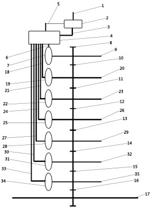
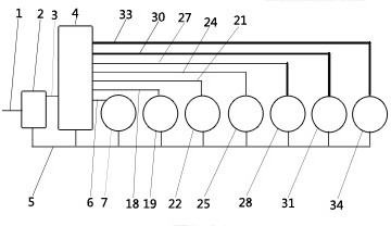
[0014]The specific embodiments of the present invention will be described in further detail by the description of the examples. Such asfigure 1 As shown, the liquid transmission, including the input shaft 1, the output shaft 17, the driven gear 16, the oil pump 2, the oil circuit controller 4, turbine, and gear gears, wherein the turbine includes a turbine 7, a reverse turbine 19, the two-stage turbine 22, the three-speed turbine 25, the four-speed turbine 28, the five-dimensional turbine 31 and the six-speed turbine 34, and they are arranged in parallel, the output shaft 17 and the first gear 8, and the reverse gear 10 is provided in parallel. The two gear 11, the three gear 12, the four gear 13, the five-speed gear 14, the six-speed gear 15, and the driven gear, wherein the first turbine 7 and the first gear 8 are connected together by a round axis 9. And fixed to the transmission housing, the reverse turbine 19 and the reverse gear 10 are connected together by the reverse wheel s...


PUM


Abstract

The invention discloses a hydraulic gearbox, which comprises an input shaft, an output shaft, an oil pump, an oil circuit controller, a gear gear and a driven gear, an oil pump is arranged between the input shaft and the oil circuit controller, and the oil pump Connected with the input shaft, between the oil pump and the oil circuit controller, there is an input oil pipe and an oil input pipe, the turbine and the gear gear are connected through the wheel shaft, and a driven gear is arranged between the gear gear and the output shaft, and each gear gear All are respectively provided with a turbine connected through a wheel shaft, and an oil circuit controller for controlling the flow of oil is arranged between the turbine and the oil pump.

Description

Technical field[0001]The present invention relates to the field of gearbox, in particular, to a hydraulic gearbox.Background technique[0002]In the car, the gearbox with clutched gearboxes and mechanical shifts, inconvenience, and often problems are not conducive to maintenance.Inventive content[0003]In response to the shortcomings of the prior art, the technical problem to be solved by the present invention is to provide a liquid transmission without a clutch and a mechanical shift, which enables shift and power output without clutch and mechanical shift.[0004]In order to solve the above technical problem, the technical solution employed in the present invention is: the liquid transmission, including an input shaft, an output shaft, an oil pump, an oil circuit controller, a gear gear, and a driven gear, the input shaft and an oil circuit. Between the controller, the oil pump is provided, the oil pump is connected to the input shaft, and there is an input tube and an output tube, and...

Claims


Application Information

Patent Timeline
Patent Type & Authority Patents(China)
IPC IPC(8): F16H47/06
CPCF16H47/06
Inventor 黎文超
Owner 黎文超
Why Eureka
Try Eureka